NVM Designer
NVM Designer is tool within Q-SYS Designer that accelerates the creation of NVM systems by providing a table-based interface for adding, organizing, and configuring NVM Routing Groups, Encoders, Decoders, and Room Combiners — all without placing or wiring components in the schematic. It is accessed from the menu bar under Tools > NVM > NVM Designer.
Traditional Q-SYS system design requires adding components to the Inventory one at a time, placing them in the schematic, and manually wiring them together. For large NVM installations with hundreds of devices — such as sports bars, convention centers, entertainment venues, and campus-wide deployments — this process is prohibitively slow. NVM Designer eliminates this bottleneck by allowing Designers to create entire NVM systems through a spreadsheet-style table where Routing Groups, Encoders, and Decoders can be added in bulk, their properties configured across multiple devices simultaneously, and their organizational structure defined through Routing Group and Room Combiner assignments.
NVM Designer and NVM Manager are both table-based tools under the Tools > NVM menu, but they serve different purposes.
-
NVM Designer operates at design time. It creates devices and configures their properties — the structural settings that define how the system is built (Name, Location, Routing Group assignment, Application mode, Audio Channels). Changes require saving and redeploying the Design.
-
NVM Manager operates at run time. It configures device controls — the operational settings that define how the system behaves (Friendly Names, source selection, driver assignment, gain levels). Changes take effect immediately without a redeploy.
The two tools are complementary. A typical workflow involves using NVM Designer to rapidly build out a large NVM system (adding devices, creating Routing Groups, assigning devices to groups), then switching to NVM Manager to configure individual device controls (assigning Friendly Names, setting up drivers, adjusting audio levels, selecting sources) and manage the system once it's running.
NVM Designer is one of three methods for building NVM systems, all of which are compatible and interoperable.
| Method | Description | Best For |
|---|---|---|
|
NVM Designer (recommended) |
Create Routing Groups, Encoders, and Decoders through the table-based tool. Devices are added to the Inventory automatically — no schematic placement or wiring required. |
Device status indicator. Shows OK, Compromised, Fault, Not Present, Missing, or Initializing. |
|
Routing Group Abstraction (manual) |
Manually add NVM Encoders, Decoders, and Routing Groups to the Inventory, then assign devices to Routing Groups through their properties. Devices remain unplaced in the schematic. |
Designs where you want Routing Group benefits but prefer to add devices individually through the Inventory. |
|
Traditional Wiring |
Add NVM devices to the Inventory, place them in the schematic, and manually wire Mediacast connections. |
Designs that include cameras or other non-NVM Mediacast devices that require schematic wiring, or designs that mix placed and unplaced components. |
All three methods produce the same functional result; the devices, Routing Groups, and interconnections behave identically regardless of how they were created. NVM Designer simply gets you there faster for large systems.
NVM Designer is accessed from the Q-SYS Designer menu bar: Tools > NVM > Show NVM Designer.
NVM Designer opens as a separate tool window within Q-SYS Designer. Changes made in NVM Designer are immediately reflected in Q-SYS Designer's Inventory, and changes made in Q-SYS Designer's Inventory are immediately reflected in NVM Designer. The two interfaces stay synchronized.
NVM Designer is available only in Design mode, before the Design is running or emulating. Because NVM Designer modifies device properties, which are structural settings, they can only be changed when the Design is not running. To modify run-time controls while the Design is running, use NVM Manager.
NVM Designer presents its data in a table view, similar to a spreadsheet where:
-
Each row represents an NVM device. For example, an Encoder, Decoder, Routing Group, or Room Combiner, along with its subcomponents, such as AV Sources, AV Displays.
-
Each column represents a property on that device. For example, Name, Location, Routing Group assignment, Mediacast Output Count, or Audio Channels.
-
Cells are editable in Edit mode. Depending on the property type, a cell may contain a text field, a drop-down, a numeric input with +/- buttons, a toggle switch, or a tag selector for multi-value properties.
The table is organized by device type, with expandable sections for Encoders, Decoders, Routing Groups, NVM AV Sources, NVM AV Displays, and Room Combiners. Each section header shows the device count (e.g., "Encoders (6)," "NVM AV Displays (13)"). NVM AV Sources and NVM AV Displays appear as their own top-level sections — they are not nested under Encoders or Decoders. Each Encoder generates one or two AV Source entries (depending on its Application setting), and each Decoder generates one AV Display entry. These sub-device sections have their own column headers specific to AV Source or AV Display properties.
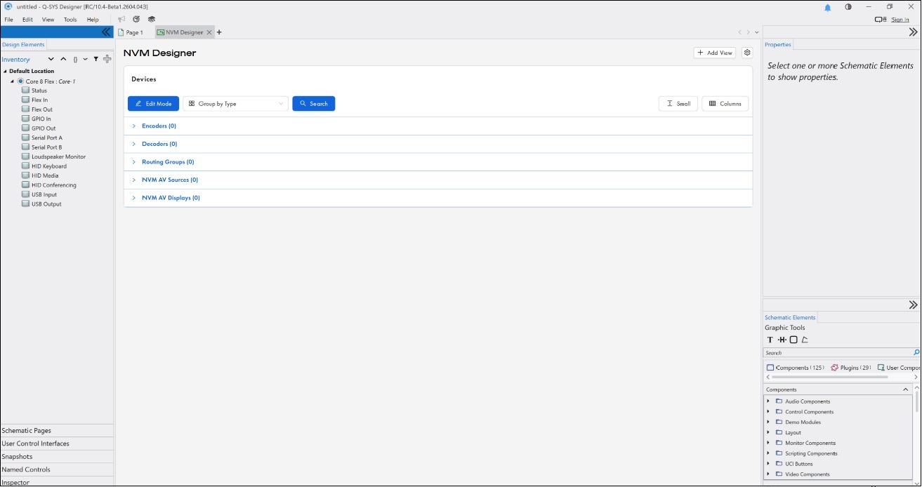
Figure 1. NVM Designer default view (view mode), grouped by Type. Device sections (Encoders, Decoders, Routing Groups, NVM AV Sources, NVM AV Displays) are collapsible and show device counts in their headers. Click Edit Mode to begin adding and configuring devices.
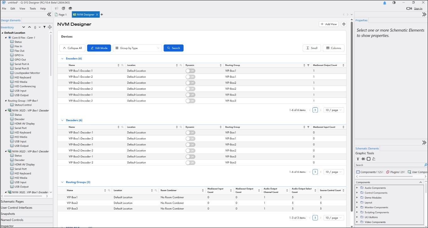
Figure 2. NVM Designer in view mode with all sections expanded, grouped by Type. Each row represents one device; each column represents a property on that device.
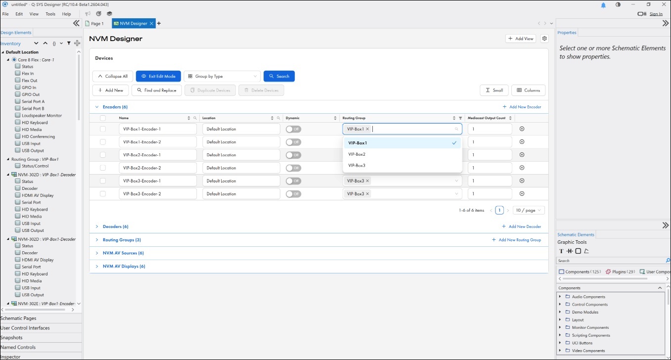
Figure 3. Edit Mode, grouped by Type. Cells become editable; the Routing Group column opens a tag selector for assigning an Encoder to one or more Routing Groups.
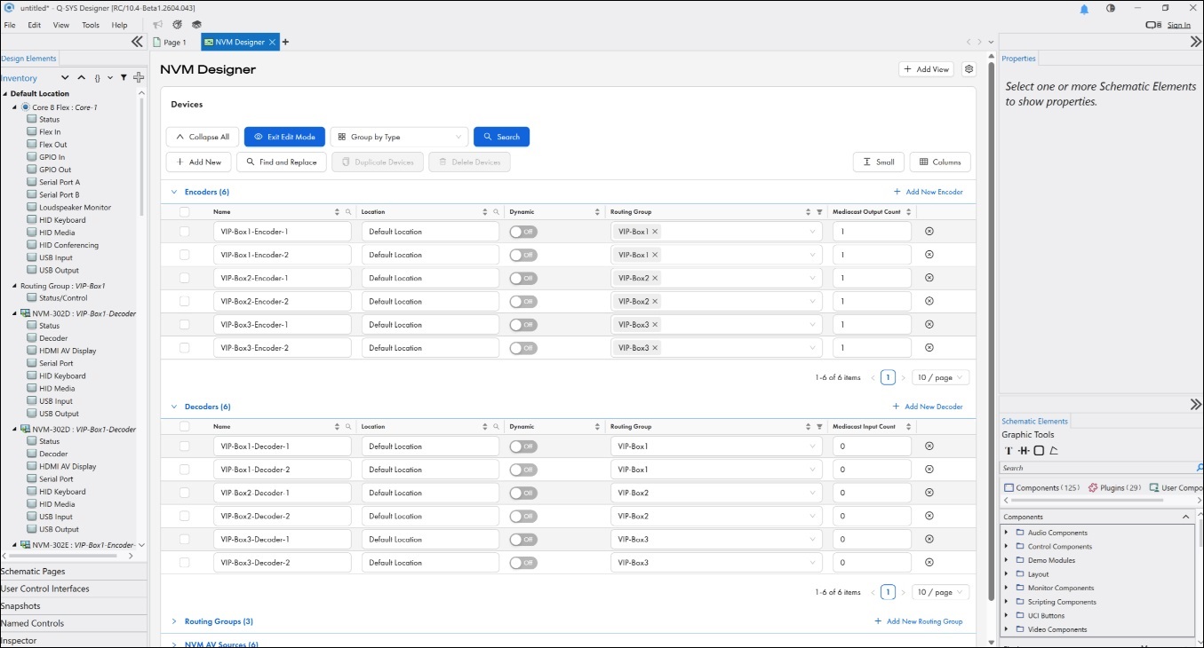
Figure 4. Edit Mode, grouped by Type, showing the Encoders and Decoders sections with their full property columns (Name, Location, Dynamically Paired, Routing Group, Mediacast counts, and more).
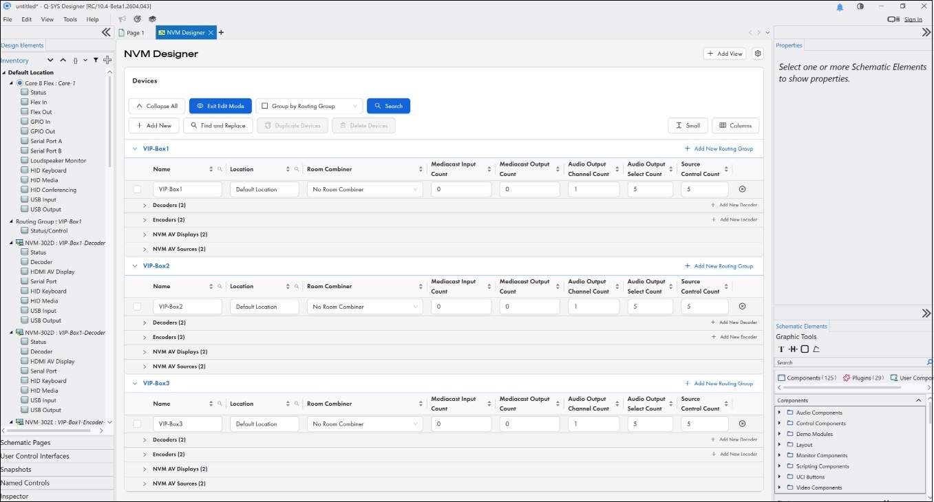
Figure 5. Edit Mode, grouped by Routing Group. Routing Group properties appear at the top of each group, followed by the Decoders, Encoders, NVM AV Displays, and NVM AV Sources assigned to that group.
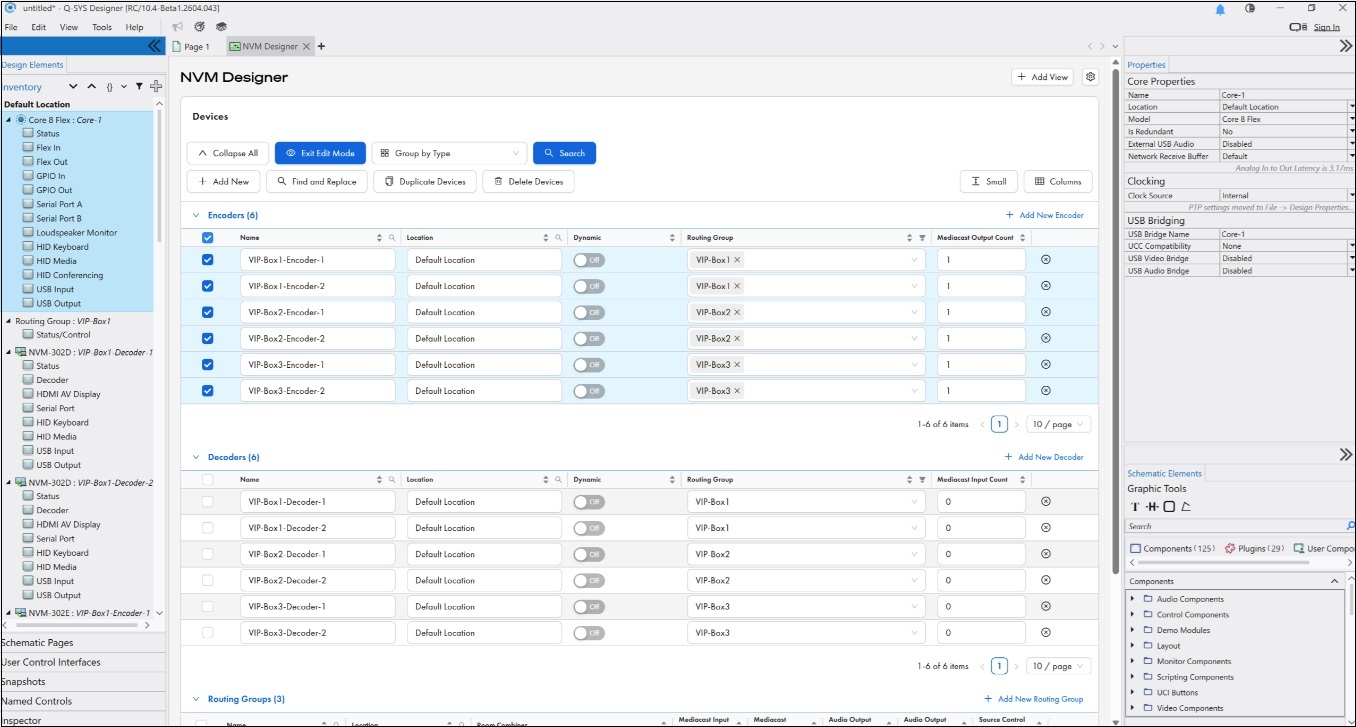
Figure 6. Edit Mode with multiple Encoders selected. Multi-selection enables Duplicate Devices and Delete Devices on the toolbar, and the Properties panel shows the shared Core Properties for the selection.
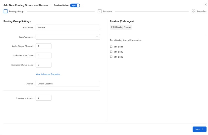
Figure 7. Add New wizard, Step 1: Routing Group and Devices. Define the Routing Group Base Name, Room Combiner assignment, Audio Output Channels, Mediacast Input/Output counts, Location, and the Number of Copies of the Routing Group to create.
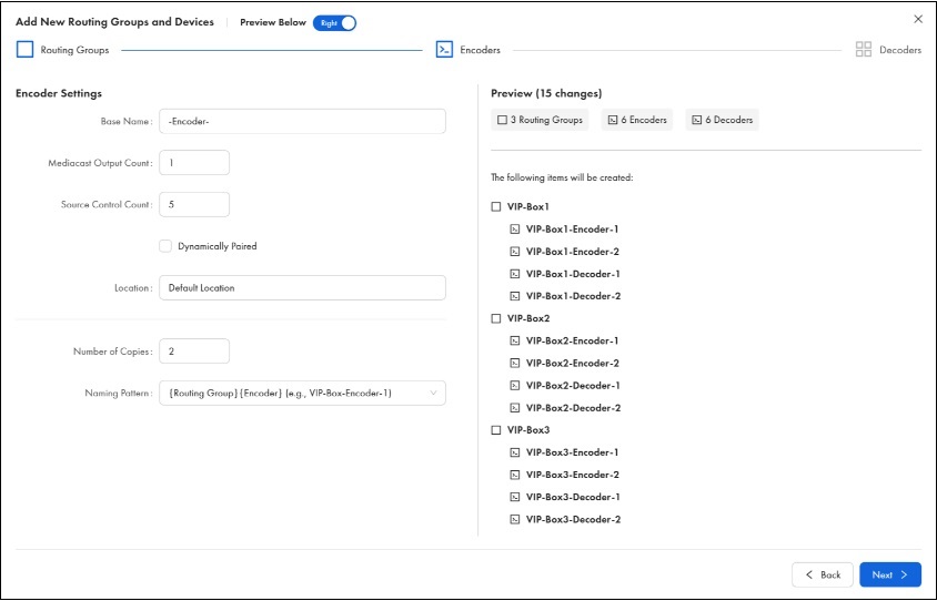
Figure 8. Add New wizard, Step 2: Encoder Settings. Configure the Base Name, Mediacast Output Count, Source Control Count, Dynamically Paired option, Number of Copies per Routing Group, and Naming Pattern. The Preview panel shows every item that will be created.
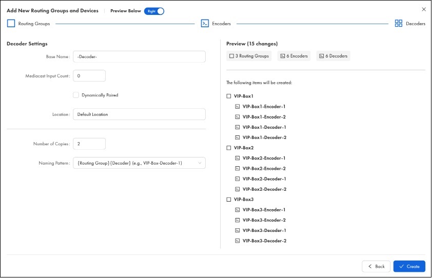
Figure 9. Add New wizard, Step 3: Decoder Settings. Configure the Base Name, Mediacast Input Count, Dynamically Paired option, Number of Copies per Routing Group, and Naming Pattern. Click ✓ Create to add all items to the Design.
Edit Mode -Cell Interaction
In Edit mode, cells are editable and their behavior depends on the property type.
| Property Type | Cell Behavior |
|---|---|
|
String (e.g., Name, Location) |
Click the cell to enter or modify text directly. |
|
String from a list (e.g., Routing Group assignment) |
Click the cell to open a drop-down of available options. |
|
Integer (e.g., Audio Channels, Source Control Count) |
Click the cell and use the +/- buttons or type a numeric value directly. |
|
Multiple items from a list (e.g., Encoder Routing Group assignment — Encoders can belong to multiple Routing Groups) |
Click the cell to open a tag selector where you can search for and select multiple values. |
|
Boolean (e.g., Is Required, Dynamically Paired) |
Click the toggle switch to change between Yes / No or Enabled / Disabled. |
Note: When multiple cells in the same column are selected and you edit one of them, the change is applied to all selected cells — enabling bulk editing across multiple devices.
Edit Mode Toolbar
When Edit Mode is active, a secondary toolbar appears below the main toolbar with the following buttons:
|
Button |
Description |
|---|---|
|
Add New |
Opens the 3-step wizard to create a new Routing Group with Encoders and Decoders. |
|
Find and Replace |
Opens the bulk renaming tool for search-and-replace across device names and properties. |
|
Duplicate Devices |
Duplicates the currently selected device rows, including all their properties. |
|
Delete Devices |
Deletes the currently selected device rows after a confirmation dialog. |
Per-Section Add Buttons
In Edit Mode, each device section header displays an inline add button — for example, "+ Add New Encoder" in the Encoders section header and "+ Add New Decoder" in the Decoders section header. These allow you to add individual devices directly to the table without going through the full 3-step Add New procedure. This is useful when you need to add a few more Encoders or Decoders to an existing Routing Group.
Table Features
Sorting
Click any column header to sort all rows by that column's values. The first click sorts ascending (A–Z or lowest to highest); the second click sorts descending (Z–A or highest to lowest). When the table is grouped by Routing Group or Room Combiner, sorting within one group applies the same sort to all groups.
Grouping
The Group by option at the top of the table allows you to organize devices into logical groupings.
| Group By | Description |
|---|---|
|
Type (default) |
Groups devices by type — all Encoders together, all Decoders together, all Routing Groups together, all NVM AV Sources together, all NVM AV Displays together. Shows properties for all devices. |
|
Routing Group |
Groups devices by Routing Group, then by type within each group. Shows Routing Group properties at the top of each group, followed by the Encoders and Decoders assigned to that group. |
|
Room Combiner |
Groups devices by Room Combiner, then sub-groups by Routing Group and type. Shows Room Combiner properties at the top of each combiner group. |
Search and Filter
The search bar at the top of the table allows you to find devices or dtypoevice properties by matching a text string. As you type, suggestions appear with tags identifying which property matched (e.g., Name, Location, Routing Group), so you can filter on exactly what you need. The table filters in real time as you type.
Column Management
Columns can be customized to show only the properties relevant to your current task.
-
Show / Hide columns — Use the column selector to check or uncheck individual columns. Different column options are available depending on the device type you are viewing.
-
Reorder columns — Drag column headers left or right to rearrange them in any order.
-
Resize columns — Drag the border between column headers to adjust column width.
Row Height
Row height can be adjusted to accommodate the data density you prefer.
Pagination
For large designs with many devices, the table is paginated. The page size and current page are displayed at the bottom of the table.
Device Selection
You can select one or more device rows using the row check boxes. Selection is used for bulk editing, copy / paste operations, and deletion.
Settings Gear Icon
In Edit Mode, each Encoder and Decoder row displays a gear icon at the far right of the row. Clicking this icon opens the device-specific settings panel for that device.
Views
NVM Designer supports views, which allow you to save a specific table configuration as a named view that can be recalled at any time.
Default View
The Default view is a pre-set view that comes out of the box. It provides a standard starting configuration. The Default view always resets back to its original configuration and cannot be permanently modified.
Custom Views
Custom views are user-created views that save your preferred table configuration. You can create multiple custom views for different tasks.
To create a custom view, configure the table the way you want it (grouping, visible columns, column order, filters), then click Add View and give it a name. The view appears as a tab across the top of the NVM Designer window for quick access.
Custom views support the following operations:
| Operation | Description |
|---|---|
|
Save |
Saves changes to the current view. |
|
Rename |
Click the view name and select Rename from the menu. |
|
Delete |
Click the view name and select Delete from the menu. |
Note: When you edit columns, filters, or other table settings, changes are not automatically saved to the current view. You must explicitly select Save to persist your changes.
The Add New button, available in Edit mode, allows you to create Routing Groups and its associated Encoders and Decoders in three steps.
The Preview Below / Right toggle at the top controls the layout of the Preview panel, which appears on all three steps. The Preview panel displays a live summary as you create Routing Groups, Encoders, and Decoders, updating automatically as you change settings.
Navigation for Steps 1 and 2 show Back and Next buttons. Step 3 replaces Next with ✓ Create to commit all items.
The Edit mode also allows you to add individual devices directly in the table. This useful when you need to add a few more Encoders or Decoders to an existing Routing Group.
-
Routing Group and Devices. Define the Routing Group and the quantity of devices to add.
Note: Audio Output Select Count, Source Select Count, and Source Control Count are hidden by default under View Advanced Properties. Click the link to reveal them.
Field
Type
Default
Description
Base Name
Text field
Routing Group
Name for the Routing Group. Sequential numbering appended for multiple copies.
Room Combiner
Drop-down
none
Assigns the Routing Group to an existing Room Combiner.
Audio Output Channels
Integer
1
Number of audio output channels from the Routing Group to the Core.
Mediacast Input Count
Integer
0
Number of Mediacast input pins on the Routing Group.
Mediacast Output Count
Integer
0
Number of Mediacast output pins on the Routing Group.
Audio Output Select Count
Integer
0
Number of audio output selector rows.
Source Select Count
Integer
0
Number of source selector rows.
Source Control Count
Integer
5
Number of source control command rows.
Location
Text field
Default Location
Location identifier for the Routing Group.
Number of Copies
Integer
1
Number of Routing Groups to create with these settings.
-
Encoder Settings. Configure properties that will be applied to all Encoders being created.
Field
Type
Default
Description
Base Name
Text field
Encoder
Name for the Routing Group Sequential numbering appended for multiple copies.
Mediacast Output Count
Integer
1
Number of Mediacast output pins on the Encoder.
Source Control Count
Integer
5
Number of source control command rows.
Dynamically Paired
Checkbox
Unchecked
When enabled, the device does not require a specific physical NVM to be assigned at design time. Instead, it is paired to a physical device at runtime when discovered on the network.
Location
Text field
Default Location
Location identifier.
Number of Copies
Integer
1
Number of Encoders to create per Routing Group.
Naming Pattern
Drop-down
{Encoder} (e.g., Encoder1)
Controls how copies are named.
Note: Each Mediacast output uses two multicast addresses — one for the main stream and one for the preview stream. In NVM-E1 mode, each encoder uses two multicast addresses. In NVM-E2 mode, each encoder uses four. These addresses are drawn from the Video Endpoints multicast address range configured in Core Manager > Network > Multicast. The default range supports up to 256 multicast streams per Core. If your design approaches this limit, use Manual mode in Core Manager to specify a wider range. For more information, see Network > Multicast.
Note: The NVM-E2 requires a separate license. Ensure appropriate NVM-E2 license is applied to your Core before deploying.
-
Decoder Settings. Configure properties that will be applied to all Decoders being created.
Field
Type
Default
Description
Base Name
Text field
Decoder
Name for the Routing Group. Sequential numbering appended for multiple copies.
Mediacast Input Count
Integer
0
Number of Mediacast input pins on the Decoder.
Dynamically Paired
Checkbox
Unchecked
When enabled, the device does not require a specific physical NVM to be assigned at design time. Instead, it is paired to a physical device at runtime when discovered on the network.
Audio Output Select Count
Integer
0
Number of audio output selector rows.
Location
Text field
Default Location
Location identifier.
Number of Copies
Integer
1
Number of Decoders per Routing Group.
Naming Pattern
Drop-down
{Decoder} (e.g., Decoder1)
Controls how copies are named.
Inline Editing
In Edit mode, click any editable cell in the table to modify its value. Changes take effect immediately in Q-SYS Designer's Inventory.
Muiti-Row Editing
Select multiple rows using their checkboxes, then edit a cell in one of the selected rows. The change is applied to all selected rows in that column. This is especially useful for applying the same property value across many devices, for example, setting all Decoders in a Routing Group to the same audio channel count.
Find and Replace
The Find and Replace button, available in Edit mode, provides a bulk renaming tool. Enter a search string and a replacement string, and NVM Designer shows a preview of all matching changes before you apply them. This is especially useful for renaming large groups of devices, for example, replacing "Zone" with "Room" across all device names.
Copy and Paste
NVM Designer supports copy and paste operations for both properties and entire devices.
-
Copying cells (one or more adjacent cells selected) — copies only the property values. Paste applies the values to matching cells in the target selection.
-
Copying entire rows (one or more rows selected) — copies the device and its properties. Paste creates a duplicate device. Names are automatically incremented to avoid duplicates (e.g., "Lobby-Dec1" becomes "Lobby-Dec2").
-
Copying a Routing Group row — copies the Routing Group and all devices within it. Paste creates a complete duplicate of the Routing Group with all its Encoders and Decoders, with names incremented.
Deleting Devices
Select one or more devices and click the Delete button. A confirmation dialog appears showing the count of selected items. Deleting a device removes it from the Q-SYS Designer Inventory.
Assigning Devices to Routing Groups
Devices can be assigned to Routing Groups in several ways.
-
During creation — The Add New automatically assigns devices to the Routing Group being created.
-
Via the table — Edit the Routing Group column on a device row to assign or reassign it.
-
Via drag and drop — In a Group by Routing Group view, drag Encoder or Decoder rows from one Routing Group section to another. Encoders can be added to multiple Routing Groups; Decoders are moved, they can belong to only one.
-
Via bulk selection — Select multiple devices and use the Assign to Routing Group option to assign them all at once.
NVM Designer exposes the design-time properties for each device type. These are the structural settings that define how the device is configured within the Design and not the run-time controls, which are managed through NVM Manager.
Encoder Properties
| Property | Type | Description |
|---|---|---|
|
Name |
String |
Unique name for the Encoder. |
|
Location |
String |
Location identifier. |
|
Is Required |
Boolean |
Whether the Encoder is required for the Design to run. |
|
Dynamically Paired |
Boolean |
Whether the Encoder uses dynamic peripheral pairing. When enabled, the device does not require a specific physical NVM to be assigned at design time; instead, it is paired to a physical device at runtime when discovered on the network. |
|
Routing Group(s) |
Multi-select |
Routing Groups the Encoder is assigned to. Encoders can belong to multiple Routing Groups. |
|
Application |
Drop-down |
Selects the Encoder's application mode: NVM-E1 (single Mediacast output; HDMI Input Config is selectable) or NVM-E2 (dual Mediacast outputs; HDMI Input Config shows N/A). |
|
HDMI Input Config |
Drop-down |
Configures the HDMI input arrangement. Available when Application is NVM-E1: 1×1 4K60 (one HDMI input at 4K 60Hz) or 2×1 4K30 (two HDMI inputs at 4K 30Hz, switched to one output). Shows N/A when Application is NVM-E2. |
|
Mediacast Output Count |
Integer |
Number of Mediacast output pins on the Encoder. Determined by the Application setting: NVM-E1 = 1 output; NVM-E2 = 2 outputs. |
Note: The relationship between Application, HDMI Input Config, and Mediacast Output Count:
-
NVM-E1 + 1×1 4K60 = 1 HDMI source → 1 Mediacast output (single source, single stream).
-
NVM-E1 + 2×1 4K30 = 2 HDMI sources → 1 Mediacast output (two sources, switched to one stream).
-
NVM-E2 = 2 HDMI sources → 2 Mediacast outputs (two sources, two independent streams). HDMI Input Config is not applicable.
Note: The NVM-E2 requires a separate license. Ensure appropriate NVM-E2 license is applied to your Core before deploying.
Multi-Room NVM System
A common NVM design starts with a set of rooms, Routing Groups, each with its own Encoders and Decoders.
Creating a Multi-Room NVM System
-
Open NVM Designer. Go to Tools > NVM > Show NVM Designer.
-
Enter Edit Mode. Click Edit Mode.
-
Create the first Routing Group. Click Add New. Enter the Routing Group name (e.g., "Lobby"), location, number of Encoders, and number of Decoders. Configure Encoder and Decoder settings in the subsequent steps. Click Create.
-
Repeat for each room. Click Add New again for each additional Routing Group (e.g., "Bar Area," "VIP Lounge," "Main Floor"). Each creates a complete Routing Group with its Encoders and Decoders in one pass.
-
Fine-tune properties. After all Routing Groups are created, use the table to adjust individual device properties. For example, select all Decoders in the Bar Area and set their Audio Channels to 2.
-
Rename devices. Use Find and Replace to bulk rename devices. For example, replace the default auto-generated names with more descriptive ones.
-
Set up Room Combiners. If rooms need to be combinable (divisible spaces), assign Routing Groups to Room Combiners using the Room Combiner column.
-
Exit Edit Mode. Click Exit Edit Mode when finished.
Duplicating Routing Groups
When multiple rooms have similar configurations, create one Routing Group, configure its properties, then copy and paste it. This is significantly faster than creating each Routing Group from scratch when they share the same structure.
-
Select the Routing Group row in the table.
-
Copy the row. The entire Routing Group and its devices are copied.
-
Paste. A duplicate Routing Group is created with all the same Encoders, Decoders, and properties. Names are auto-incremented.
-
Rename the duplicated Routing Group and its devices as needed.
Adding Shared Sources Across Routing Groups
Some sources (e.g., a single ESPN tuner) need to be available in multiple Routing Groups. To configure this:
-
In the table, locate the Encoder for the shared source.
-
Edit the Routing Group(s) column for that Encoder.
-
Select all Routing Groups that should have access to this source.
The Encoder's source automatically appears in the Source Selector List (SSL) of every AV Display in each assigned Routing Group.
NVM Designer is a tool, not a schematic component — it does not have its own input or output pins. However, when you create devices in NVM Designer, the following sub-components are automatically added to the Q-SYS Designer Inventory for each device type.
Encoder (NVM-302E) — Sub-Components Created in Inventory
| Sub-Component | Condition | Description |
|---|---|---|
|
Status |
Always |
Device status indicator. Shows OK, Compromised, Fault, Not Present, Missing, or Initializing. |
|
HDMI AV Source 1 |
Always |
First HDMI input source. |
|
HDMI AV Source 2 |
NVM-E2, or NVM-E1 with HDMI Input Config = 2×1 4K30 |
Second HDMI input source. Only appears when the Application / HDMI Input Config supports two inputs. |
|
Serial Port A |
Always |
First RS-232 serial port. |
|
Serial Port B |
Always |
Second RS-232 serial port. |
|
HID Keyboard |
Always |
HID keyboard emulation. |
|
HID Media |
Always |
HID media controls. |
|
USB Input |
Always |
USB input. |
|
USB Output |
Always |
USB output. |
Decoder (NVM-302D) — Sub-Components Created in Inventory
| Sub-Component | Condition | Description |
|---|---|---|
|
Status |
Always |
Device status indicator. Shows OK, Compromised, Fault, Not Present, Missing, or Initializing. |
|
HDMI AV Display |
Always |
First HDMI input source. |
|
Serial Port A |
Always |
First RS-232 serial port. |
|
Serial Port B |
Always |
Second RS-232 serial port. |
|
HID Keyboard |
Always |
HID keyboard emulation. |
|
HID Media |
Always |
HID media controls. |
|
USB Input |
Always |
USB input. |
|
USB Output |
Always |
USB output. |
NVM Designer is a tool, not a schematic component. It does not have configurable properties in the Properties pane of Q-SYS Designer.
NVM Designer remembers user preferences (selected view, table configuration) between sessions.
NVM Designer is a tool, not a schematic component. It does not have its own control panel.
NVM Designer creates and configures the design-time properties of NVM devices. For run-time controls (Friendly Names, source selection, drivers, gain, mute, and operational settings), use NVM Manager.
NVM Designer does not have control pins. It is a design-time tool, not a schematic component.
To access NVM device controls programmatically via Lua scripting or external control protocols, use the control pin names documented in each NVM component's help topic—Encoder (NVM-302E), Decoder (NVM-302D), Status/Control (NVM Routing Group), NVM Proxy.