Status/Control (NVM Routing Group)
The Routing Group is a Q-SYS Designer Inventory component that represents a virtual matrix of NVM Encoders and Decoders. It provides source selection, source control, audio output routing, and Mediacast I/O for all NVM devices assigned to the group — without requiring those devices to be placed or wired in the schematic.
Think of a Routing Group as a virtual video switcher for a physical area. Encoders assigned to the Routing Group provide the available sources; Decoders assigned to it provide the displays. Every display in the Routing Group can independently select, via the NVM Proxy, any source from the group's Source Selection List (SSL). Routing Groups can be assigned to a Room in a Room Combiner to support divisible spaces — when rooms are combined, their SSLs merge automatically. Serving as the central organizational element for NVM‑based designs, Routing Groups provide the ability to quickly assemble, label, and control large video routing systems while maintaining a clean and efficient schematic.
-
Simplified design — NVM Encoders and Decoders don't need to be placed in the schematic or wired together. Assigning them to a Routing Group creates the full matrix interconnection automatically.
-
Reduced audio network channels — Instead of streaming audio from every decoder to the Core, each Routing Group sends only one audio stream (up to 8 channels) using AES-67. The audio source can be dynamically selected from any decoder in the group.
-
Scalability — Even single-room designs benefit from Routing Groups. For large systems with hundreds of displays, Routing Groups are essential.
-
Divisible spaces — Routing Groups integrate with the Room Combiner component. When rooms are combined, SSLs and audio merge across the combined groups.
-
Encoders can belong to multiple Routing Groups. Decoders can belong to only one.
-
Mediacast Input pins can be added to bring external Mediacast sources (cameras, NV-32-H, System Link) into the Routing Group's matrix.
-
Mediacast Output pins can be added to send the Routing Group's selected source to external destinations. Each Mediacast Output is also routed back into the virtual matrix so displays can use it as a source — this provides a simple method for grouping displays to a common source.
-
The Routing Group component does not control NVM hardware directly. It represents a grouping of NVM devices and provides the controls for source selection, source control, and audio output routing. The NVM Proxy provides direct control of the devices in each routing group.
The Source Selection List (SSL) is the collection of sources available for selection on any output device within a Routing Group. The SSL is populated from the following:
-
NVM Encoders assigned to the Routing Group, listed by their Friendly Names.
-
Mediacast Inputs wired to the Routing Group, listed by either their local Friendly Name or the upstream source's Friendly Name.
-
Mediacast Outputs belonging to the Routing Group, available to AV Displays only — not to other Mediacast Outputs, to prevent routing loops.
-
Core Graphics images positioned at the top or bottom of the list, or excluded entirely, based on the Graphics in Selector List control.
The SSL is always alphabetically sorted (except for Graphics, which are grouped together at the configured position). It updates dynamically whenever Friendly Names change or Routing Groups are combined or separated. Friendly Names do not need to be unique, but duplicate names can create ambiguity when Routing Groups are combined.
Rather than streaming audio from every decoder to the Core, each Routing Group uses a single AES-67 unicast stream (up to 8 channels) from the selected decoder. This dramatically reduces network audio channel usage in large systems.
The Audio Output selector controls determine which AV Display's decoder provides audio to the Routing Group's Breakaway Channel output pin. When the Audio Output Channels property is set to 1 (the default) and the source provides two or more channels, the decoder automatically down-mixes the first two channels to mono before transmission.
When Routing Groups are combined via a Room Combiner, only one AES-67 receiver in the combined group is active. The remaining receivers are muted to prevent duplicate audio and unwanted gain. The downstream Room Combiner handles mixing audio across the combined rooms.
Routing Groups can be assigned to rooms within a Room Combiner component to support divisible spaces. When rooms are combined:
-
Source Selection Lists merge across all combined Routing Groups, giving every display access to sources from all combined rooms.
-
Audio output controls synchronize — selecting an audio source in any combined Routing Group applies the change across all of them.
-
The Routing Groups Combined control displays which room numbers are currently combined (e.g., "1,3,6"), enabling scripts and UCIs to respond to room state changes.
When rooms are separated:
-
Source Selection Lists (SSL) revert to only the sources within each individual Routing Group.
-
Displays whose current source is still valid continue unchanged.
-
Displays whose source is no longer available automatically switch to the first valid source in their selector button rows. If no button source is valid, the display switches to the first source in its Source Selection List.
Note: The Routing Group does not mix audio internally — its audio outputs must be wired to a Room Combiner component in the schematic for audio combining to occur.
Divisible rooms — Source Selection Lists merge when rooms combine. Three Routing Groups (Room1, Room2, Room3) are connected to a Room Combiner. When rooms are separated, each display sees only sources from its own Routing Group. When rooms are combined, the Source Selection Lists merge — every display in the combined space can select sources from all combined rooms. The All Outputs source selector (top right) shows the expanded SSL with sources from all three rooms.
Mediacast Inputs
Mediacast Inputs bring external Mediacast sources — such as cameras, NV-32-H devices, and System Link receivers — into the Routing Group's virtual matrix. Each input is added to the Source Selection List, making it available to all displays and Mediacast Outputs in the Routing Group. Each input can be assigned a local Friendly Name that appears in selector lists.
Mediacast Outputs
Mediacast Outputs serve two purposes:
-
They provide a wireable output pin for sending the Routing Group's selected source to external destinations (another Routing Group, System Link Tx, NV Series device).
-
They are automatically routed back into the virtual matrix as a source, allowing AV Displays to select them — this provides a simple method for creating Display Groups where multiple displays share a common source.
Each Mediacast Output has its own source selector and source control, independent of other outputs and the All Outputs control.
The All Outputs tab provides simultaneous control of every AV Display and Mediacast Output in the Routing Group. Selecting a source here switches all outputs to that source at once. If an individual output is later changed to a different source, the All Outputs selector goes blank, indicating that outputs no longer share a common source.
When Routing Groups are combined via a Room Combiner, the All Outputs control extends across all combined groups. If outputs are already set to different sources at the time of combining, no automatic changes occur — the All Outputs selector remains blank until a common source is explicitly selected.
A Display Group is a set of displays that share the same source and switch together. This is useful in scenarios such as a sports bar where multiple TVs need to show the same game, or a corporate lobby where all screens display the same content.
Within a single Routing Group:
-
Add a Mediacast Output to the Routing Group.
-
Assign each display you want grouped to use that Mediacast Output as its source.
-
Change the Mediacast Output's source — all grouped displays follow automatically.
Across multiple Routing Groups:
Wire the originating Routing Group's Mediacast Output to another Routing Group's Mediacast Input. Displays in the second Routing Group can then select that input as their source, extending the Display Group across rooms or zones.
Display Groups are dynamic — displays can join or leave at any time simply by changing their source selection. Q-SYS Snapshots provide a convenient way to reconfigure Display Groups for different scenarios, such as switching from morning news to afternoon sports.
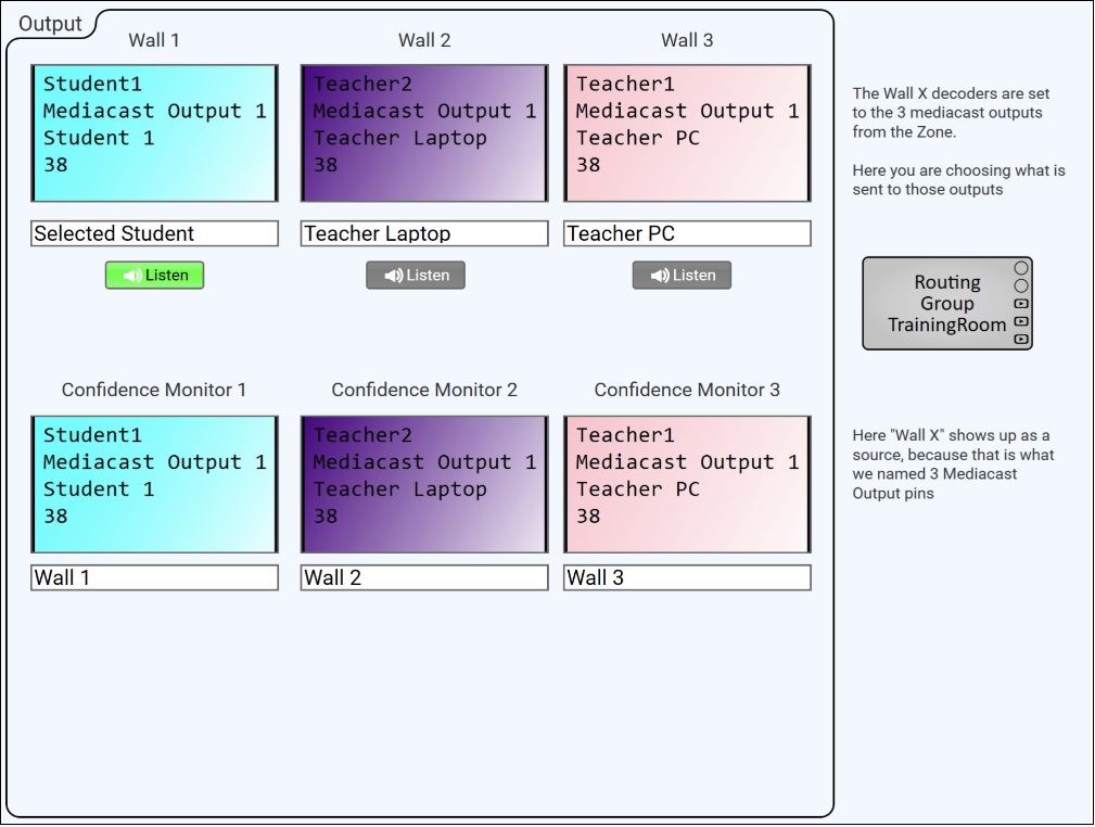
Display Groups using Mediacast Outputs — training room UCI. Three Mediacast Outputs (Wall 1, Wall 2, Wall 3) serve as Display Group sources for the TrainingRoom Routing Group. The top row shows the Mediacast Output source selectors, each choosing which source feeds that wall group (Selected Student, Teacher Laptop, Teacher PC). The bottom row shows three Confidence Monitors — individual displays that select one of the three Mediacast Outputs ("Wall 1," "Wall 2," "Wall 3") as their source, automatically following whichever source the wall group is set to.
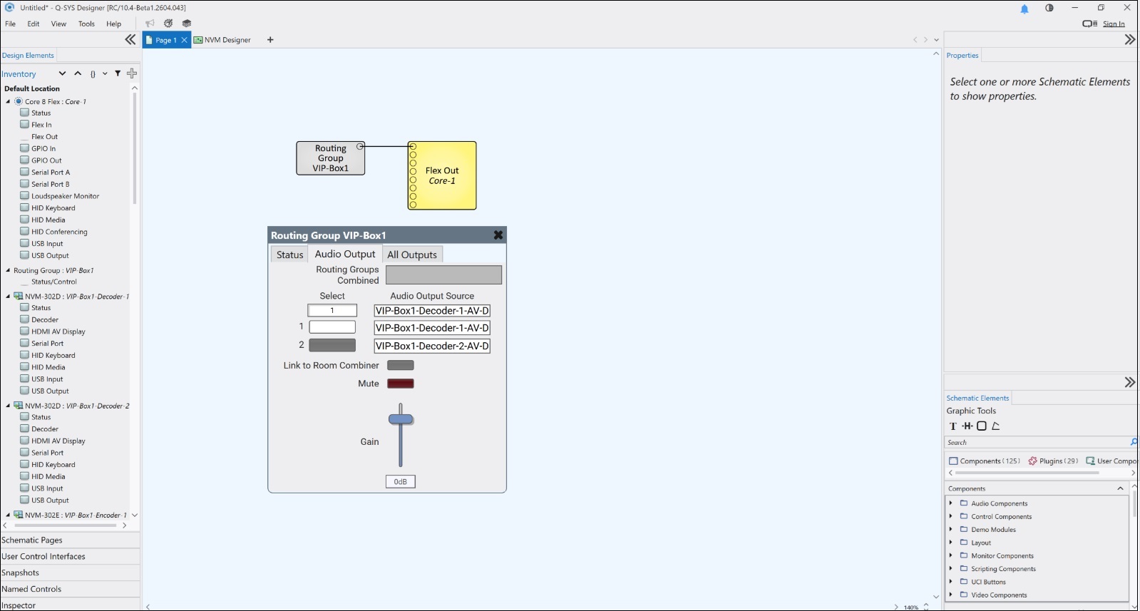
Routing Group with Audio Output controls. A single Routing Group (VIP-Box1) wired to a Flex Out component in the schematic. The Audio Output tab is open, showing the audio source selector with two AV Displays (VIP-Box1-Decoder-1 and VIP-Box1-Decoder-2), Link to Room Combiner toggle, Mute button, and Gain fader. The Routing Groups Combined field is blank because no Room Combiner is assigned. The Inventory pane (left) shows the Routing Group's assigned Decoders and Encoder.
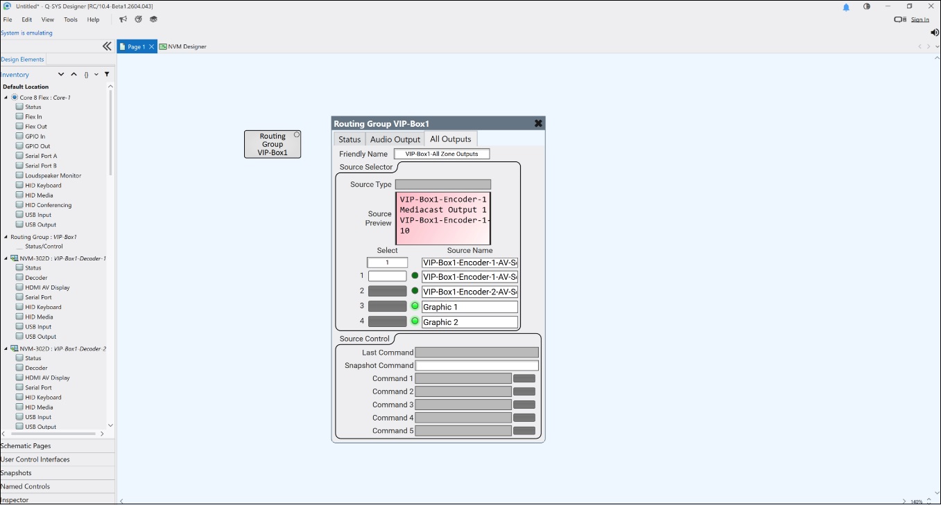
Routing Group All Outputs tab in Emulation mode. The same Routing Group (VIP-Box1) with the All Outputs tab open. The Source Selector shows four sources: two Encoders (VIP-Box1-Encoder-1-AV-S, VIP-Box1-Encoder-2-AV-S) with green active LEDs, plus Graphic 1 and Graphic 2. The Source Preview window displays a live preview of the selected source. Below the selector, the Source Control section provides five configurable command rows with Send buttons.
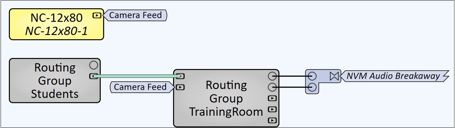
Inter-Routing Group Mediacast wiring. Two Routing Groups connected via Mediacast. An NC-12x80 camera's Mediacast output ("Camera Feed") is wired to Routing Group Students, whose Mediacast output is wired to Routing Group TrainingRoom's Mediacast input — making the camera feed available as a source to all displays in TrainingRoom. The TrainingRoom Routing Group's Breakaway Channel outputs are wired to an NVM Audio Breakaway component for audio routing to the Core DSP.
Input Pins
Mediacast Input 1 – n
Each pin accepts an external Mediacast source (e.g., camera, NV-32-H, System Link) and adds it to the Routing Group's virtual matrix. The number of pins is determined by the Mediacast Input Count property. All displays and Mediacast Outputs in the Routing Group can select these inputs as sources.
Output Pins
Breakaway Channel 1 – n
Provides the Routing Group's breakaway audio output to the Q-SYS Core DSP. The selected decoder within the Routing Group breaks away its HDMI or USB-C display audio and sends it to the Core via AES-67. The audio can then be routed to amplifiers, Room Combiners, or other audio components. The number of pins is determined by the Audio Output Channels property. When set to 1 channel and the source has 2 or more channels, the decoder down-mixes the first two channels to mono.
Mediacast Input 1 – n
Each pin provides a Mediacast output that can be wired to external destinations (another Routing Group, System Link Tx, NV Series device). Each Mediacast Output is also routed back into the virtual matrix as a source, allowing displays to select it — useful for grouping displays to a common source. The number of pins is determined by the Mediacast Output Count property.
Properties are displayed in the right-side pane of Q-SYS Designer when the Routing Group component is selected.
Routing Group Properties
Name
The Name may contain ASCII letters 'a' through 'z' (case-insensitive), the digits '0' through '9', and the hyphen. Names cannot begin or end with a hyphen. No other symbols, punctuation characters, or blank spaces are permitted.
Location
User-defined name that groups the component with other components in the same physical location, for example, "Casino West".
Graphic Properties
Label
User-defined text that appears next to the component on the Schematic. Changing the label does not affect the component name or system behavior.
Position
Specifies the X and Y coordinates of the component on the Schematic. The values update automatically when you move the component, and can be edited to place the component at an exact location.
Fill
Sets the background color of the component block on the Schematic. This is for visual organization only and does not affect system operation.
Script Access
Code Name
Displays the currently assigned name for control access. You can use the auto-assigned name or customize it. Q-SYS will automatically check all Code Names in the design to ensure name is unique.
Script Access
Defines whether the component will be accessible by script and/or externally, or not at all. Choices include All, External, None (default), and Script.
- None (default) - Not accessible by any script, plugin, or by Q-SYS Remote Control Protocol (QRC).
- Script - Can be accessed by scripts, such as Text Controller, Block Controllers, and plugins only.
- External - Can only be accessed by 3rd party controls systems using component commands from the Q-SYS Remote Control Protocol (QRC).
- All - No restrictions, can be accessed by 3rd party control systems via Q-SYS Remote Control Protocol (QRC), or script objects or plugin objects.
Tip: Use Script Programmer Mode to quickly view the Script Access setting directly on the component in the design schematic without the need to disconnect from the Q-SYS Core processor.
Routing Group Configuration Properties
Audio Output Channels
Audio Output Channels determines how many audio channels the Routing Group provides on its Audio Output pin. The Routing Group uses a single AES‑67 audio stream from the Core, supporting up to 8 channels. When set to one channel (the default), any multi‑channel HDMI or USB‑C audio from an NVM Decoder is automatically downmixed to mono before transmission.
Source Select Count
Source Select Count sets the number of Source Selector Rows available in the Routing Group’s control panel. Each row represents one selectable AV source within the Routing Group, which provides the ability to choose how many sources should appear in the selector list for that Zone. Increasing this value adds more selector buttons; decreasing it limits the list to only the most relevant sources.
Source Select Image Buttons
Source Select Image Buttons enables visual preview buttons in the Routing Group’s source selector. When enabled, each selector button displays a low‑frame‑rate Mediacast preview stream. These preview buttons can also be used on UCIs.
Room Combiner
Room Combiner links the Routing Group to a specific Room Combiner component and room number. This allows multiple Routing Groups (often representing individual rooms or areas) to follow the Room Combiner’s combine / separate state. When rooms are combined, the Routing Group automatically updates its source selector lists and proxy display lists to include sources and displays from all combined rooms. If no Room Combiner component has been added, only <None> is available. Options: <None>, (list of available Room Combiner components). Default: <None>.
Room Combiner Room Number
Sets the room number for this Routing Group within the selected Room Combiner. Each Routing Group must use a unique room number within its Room Combiner; duplicate numbers prevent the design from deploying. This property appears when a Room Combiner is assigned. Options: Integer. Default: 0.
Note: The Room Combiner is a separate component located under Schematic Elements > Components > Audio Components > Room Combiner. To use it with Routing Groups, add a Room Combiner component to the schematic, configure its Rooms and Walls properties, then wire each Routing Group's Audio Output pin to the Room Combiner's input. The Room Combiner property drop-down above will then list available Room Combiner components. For more information, see Room Combiner.
Audio Output Select Count
Audio Output Select Count sets the number of Audio Output Selector Rows available on the Routing Group’s Audio Output tab. Each row provides a button for choosing which NVM Display supplies audio to the Routing Group. Increasing this value adds more selectable audio sources; decreasing it limits the list to only the sources you want exposed.
Source Control Count
Source Control Count sets the number of Source Control Rows available in the Routing Group’s Source Control panel. Each row provides a configurable command name and a corresponding Send button, which allows the ability to expose as many source‑specific control actions as needed. Increasing this value adds more command rows; decreasing it limits the list to only the controls you want available for each selected source.
Mediacast Configuration Properties
Mediacast Input Count
Mediacast Input Count sets the number of Mediacast input pins created on a Routing Group or NVM Decoder. Each pin represents an external Mediacast source that can be wired into the design and made available to displays or outputs within the Routing Group. Increasing this value adds more Mediacast inputs to the virtual router (or physical Decoder), while decreasing it limits how many external sources can be connected and labeled in the Mediacast Inputs tab.
Mediacast Output Count
Mediacast Output Count sets the number of Mediacast output pins created on a Routing Group. Each output is added as both an input and an output to the virtual Mediacast Router, allowing it to access any source in the Routing Group and enabling AV Displays to use that output as a shared, group‑wide source. Increasing this value adds additional “OutX” tabs and corresponding control panels; decreasing it limits how many Mediacast outputs the Routing Group exposes.
For Encoders, this property determines how many Mediacast outputs the device provides based on its available AV sources.
Routing Group Control Panel
The Routing Group Control Panel is organized into multiple tabs. Some tabs are always shown, and others appear only when the corresponding feature is enabled.
| Tab Name |
When It Appears |
|---|---|
|
Status |
|
|
Audio Outputs |
Shown only when the routing group has Audio Output Channels enabled. (Audio Channels > 0) |
|
All Outputs |
Always shown. |
|
Mediacast Inputs |
Shown only when the routing group has one or more Mediacast Inputs. (Mediacast Input Count > 0) |
|
Mediacast Outputs (Out 1, Out 2, ... ) |
One tab per configured Mediacast Output. (Mediacast Output Count determines number of tabs.) |
Status Tab
| Control | Type | Description |
|---|---|---|
|
Graphics in Selector List |
Drop-down |
Determines where the Core's Graphics images (Graphics 1, Graphics 2, Graphics 3) appear in the Source Selection Lists across all displays and outputs in this Routing Group. Top places them at the top of the list, Bottom places them at the bottom, Exclude removes them from the list entirely. Options: Top, Bottom, Exclude. Default: Bottom. |
|
Status |
LED / Text |
Displays the Routing Group's overall status. Shows OK when all devices in the Routing Group are functioning normally. |
Audio Output Tab
| Control | Type | Description |
|---|---|---|
|
Routing Groups Combined |
Text (read-only) |
Shows which Routing Groups are currently combined with this one via the Room Combiner. Displays the room numbers separated by commas (e.g., "1,3,6"), ordered lowest to highest. Blank if no Room Combiner is assigned. If a Room Combiner is assigned but the group is not combined, shows only its own room number. |
|
Select |
Drop-down |
Selects which AV Display's audio is routed to the Routing Group's Audio Output pin. The list shows the Friendly Names of all AV Displays in the (combined) Routing Group. |
|
Select 1 – n |
Buttons |
Audio output selector buttons. Each button can be assigned to a different AV Display. The number of buttons is determined by the Audio Output Select Count property. |
|
Audio Output Source (per button) |
Text (read-only) |
Displays the name of the AV Display assigned to each selector button. |
|
Link to Room Combiner |
Toggle |
When enabled, links the Routing Group's Gain and Mute controls bidirectionally with the associated Room Combiner room gain control. The Routing Group must be wired to a Room Combiner component for this to function. |
|
Mute |
Toggle |
Mutes the zone's audio when linked or wired to a downstream audio device. |
|
Gain |
Fader |
Adjusts the zone's audio level when linked or wired to a downstream audio device. |
All Outputs Tab
The All Outputs tab controls all AV Displays and Mediacast Outputs in the Routing Group simultaneously. If a source is selected here, all displays and Mediacast Outputs switch to that source. If a source is changed on an individual AV Display or Mediacast Output, the All Outputs selection is broken (grayed out) while the other outputs remain on their current source.
Friendly Name
| Control | Type | Description |
|---|---|---|
|
Friendly Name |
Text |
A user-defined name for the All Outputs group. Appears in NVM Proxy selector lists. Can be changed at runtime. |
Source Selector
| Control | Type | Description |
|---|---|---|
|
Source Type |
Text (read-only) |
Displays the device type of the currently selected source (e.g., "Set-Top Box," "Media Player"). Populated from the source's Source Type control. |
|
Source Preview |
Preview Window |
Displays a live video preview of the currently selected source. |
|
Select |
Drop-down |
Selects a source by Friendly Name from the Source Selection List (SSL). The SSL is populated from the Encoders assigned to the Routing Group, plus any Mediacast Inputs and Graphics. |
|
Select 1 – n |
Buttons |
Source selector buttons. Each button can be assigned to a different source at runtime. Green LEDs indicate the currently active source. The number of buttons is determined by the Source Select Count property. |
|
Source Name |
Text (read-only) |
Displays the Friendly Name of the source assigned to each selector button. |
Source Control
| Control | Type | Description |
|---|---|---|
|
Last Command |
Text (read-only) |
Displays the most recently sent source command. |
|
Snapshot Command |
Text / Button |
Captures or recalls a command snapshot for group actions. |
|
Command 1 – n |
Text + Send Button |
Each row displays a command name and a Send button. Commands are routed upstream through the Mediacast wiring to the currently selected source device. The number of rows is determined by the Source Control Count property. |
Mediacast Inputs Tab
This tab appears when the routing group has one or more Mediacast Inputs and allows you to adjust the names that will appear for each Mediacast Input in Source Selector lists.
| Control / Pin Name |
Control Type |
Direction |
Description |
|---|---|---|---|
|
Media Inputs > Input Naming Controls |
Name / Label Fields |
Input / Output |
Friendly name assignment controls for each mediacast input source. |
Mediacast Out n Tab
Appears once for each Mediacast Output in the routing group (up to 20). Controls for these outputs use the pin name prefix, "Mediacast Output n", where n is the output number (1,2,3, ...).
Note: The Source selector buttons on each Mediacast Output page use the same name settings as the All Outputs page. If you change the name next to a selector button on one page, that name automatically updates everywhere that button appears.
| Pin Name |
Control Type |
Direction |
Description |
|---|---|---|---|
|
Mediacast Output n > Friendly Name |
Text Control |
Input / Output |
User-assigned friendly name. |
|
Mediacast Output n > Source > Select |
Source Selector Buttons |
Input / Output |
Row of source selector buttons. Each button selects one of the available sources for this output. The number of buttons matches the number of sources that have been enabled for this control (default: 4). |
|
Mediacast Output n > Source > Select by Name |
Text Select |
Input / Output |
Selects source by name. |
|
Mediacast Output n > Source > Select by Number |
Numeric Entry |
Input / Output |
Selects source by number. |
|
Mediacast Output n > Source > Active Source Name |
Text Display |
Output |
Name of the currently active source. |
|
Mediacast Output n > Source > Command 1-N > Command |
Text Trigger |
Input / Output |
Text field for naming each source control command. One field per command row. |
|
Mediacast Output n > Source > Command 1-N > Send |
Trigger |
Input |
Button that sends the selected source‑control command for this Mediacast Output. One button per command row. |
|
Mediacast Output n > Source > Last Command |
Text Display |
Output | Last executed source control command. |
|
Mediacast Output n > Source > Current Command |
Text Display |
Output | Currently active source control command. |
|
Mediacast Output n > Source > Snapshot Command |
Snapshot |
Input / Output |
Snapshot-capable source command. |
All Outputs — Source
Active
| Pin Name | Control Type |
Value |
String | Position |
Direction |
Description |
|---|---|---|---|---|---|---|
|
Active 1 – n |
LED |
0 1 |
false true |
0 1 |
Output |
Source selector button n is the active source. |
Select
| Pin Name | Control Type |
Value |
String | Position |
Direction |
Description |
|---|---|---|---|---|---|---|
|
Select 1 – n |
Button |
0 1 |
false true |
0 1 |
Input / Output |
Source selector button n. |
|
Select 1 – n Media |
Text |
— |
text |
— |
Output |
Preview media content for audio selector button n. |
|
Select 1 – n Name |
Text |
— |
text |
— |
Input / Output |
Friendly Name of source assigned to selector button n. |
|
Select by Name |
Text |
— |
text |
— |
Input / Output |
Select source by Friendly Name. |
|
Select by Number |
Integer |
— |
— |
— |
Input / Output |
Select source by SSL index. |
|
Type |
Text |
— |
text |
— |
Output |
Source Type of the currently selected source. |
All Outputs
Friendly Name
|
Pin Name |
Control Type |
Value |
String | Position |
Direction |
Description |
|---|---|---|---|---|---|---|
|
Friendly Name |
Text |
— |
text |
— |
Input / Output |
Friendly Name for All Outputs. |
Source Control
|
Pin Name |
Control Type |
Value |
String | Position |
Direction |
Description |
|---|---|---|---|---|---|---|
|
Command 1 – n Command |
Text |
— |
text |
— |
Input / Output |
Source control command string for row n. |
|
Command 1 – n Send |
Trigger |
0 1 |
false true |
0 1 |
Input / Output |
Send source control command for row n. |
|
Current Command |
Text |
— |
text |
— |
Output |
Currently executing command. |
|
Hidden Snapshot |
Text |
— |
text |
— |
Input / Output |
Hidden snapshot control. |
|
Last Command |
Text |
— |
text |
— |
Output |
Most recently sent command. |
|
Snapshot Command |
Text |
— |
text |
— |
Input / Output |
Snapshot command for group actions. |
Audio Output Source
Select
| Pin Name | Control Type |
Value |
String | Position |
Direction |
Description |
|---|---|---|---|---|---|---|
|
Select 1 – n |
Button |
0 1 |
false true |
0 1 |
Input / Output |
Audio output selector button n. |
|
Select 1 – n Media |
Text |
— |
text |
— |
Output |
Preview media content for audio selector button n. |
|
Select 1 – n Name |
Text |
— |
text |
— |
Input / Output |
AV Display name assigned to selector button n. |
Audio Controls
| Pin Name | Control Type |
Value |
String | Position |
Direction |
Description |
|---|---|---|---|---|---|---|
|
Gain |
Fader |
−100 to 20 | −100dB to 20dB |
0.000 to 1.00 |
Input / Output |
Audio output gain. |
|
Link to Room Combiner |
Button |
0 1 |
false true |
0 1 |
Input / Output |
Link gain / mute to Room Combiner. |
|
Mute |
Button |
0 1 |
unmuted muted |
0 1 |
Input / Output |
Audio output mute. |
|
Routing Groups Combined |
Text |
— |
text |
— |
Output |
Combined room numbers (e.g., "1,3,6"). |
|
Select by Name |
Text |
— |
text |
— |
Input / Output |
Select audio source by AV Display Friendly Name. |
|
Select by Number |
Integer |
— |
— |
— |
Input / Output |
Select audio source by index. |
Status
| Pin Name | Control Type |
Value |
String | Position |
Direction |
Description |
|---|---|---|---|---|---|---|
|
Graphics in Selector List |
Selector |
— |
Top, Bottom, Exclude |
— |
Input / Output |
Position of Graphics in SSL. |
|
Routing Group Status |
Text |
0–5 |
OK, Compromised, Fault, Not Present, Missing, Initializing |
— |
Output |
Routing Group status. |