NVM Manager
NVM Manager is tool within Q-SYS Designer that provides a centralized, spreadsheet-style interface for viewing, configuring, and managing every control on every NVM Encoder, NVM Decoder, and NVM Routing Group in a Design. It is accessed from the menu bar under Tools > NVM > NVM Manager.
In NVM system designs, hundreds of NVM devices can exist in the Inventory without being placed or wired in the schematic. While this simplifies system design, it also means those devices' controls are not directly accessible through the traditional schematic-based workflow — you cannot double-click an unplaced component to open its control panel. NVM Manager solves this by exposing every NVM device control in a single, consolidated table where rows represent devices and columns represent controls and settings.
NVM Manager serves two primary workflows:
-
System Design and Configuration — During the design phase, use NVM Manager to configure NVM device settings that would otherwise require placing each component into the schematic. This includes assigning Friendly Names, setting EDID preferences, configuring source, and display control drivers, as well as setting audio gain levels. NVM Manager works in both Design mode and Emulation mode, allowing Designers to set up and test configurations before deploying to a Core. Designers will often bounce between NVM Designer (for creating devices, Routing Groups, and Room Combiners) and NVM Manager (for configuring device controls) during the design process.
-
System Management and Monitoring — Once a design is running on a Core, System Managers use NVM Manager to monitor device status, troubleshoot issues (such as debugging audio gain stages across multiple devices), make configuration changes to improve operation, and manage device drivers — all without taking the system offline. Changes made in NVM Manager—including previews of sources and displays—take effect dynamically at runtime without requiring a redeploy.
NVM Manager is not intended to be a daily control method for operating running systems—UCIs and the NVM Proxy component are better suited for that. Instead, it serves as a configuration and management power tool for those who design and maintain NVM systems.
Tip: Because many NVM controls are configuration settings that are set once and rarely changed, NVM Manager is especially useful during initial commissioning. Once the system is running, most day-to-day operation happens through UCIs and NVM Proxies, with NVM Manager reserved for maintenance and troubleshooting.
NVM Manager and NVM Designer are both table-based tools under the Tools > NVM menu, but they serve different purposes:
-
NVM Designer is focused on creating NVM systems — it accelerates the process of adding Encoders, Decoders, Routing Groups, Room Combiners, and their interconnections to a Design. NVM Designer operates in an Edit Mode where you can add, delete, duplicate, and reorganize devices and groupings.
-
NVM Manager is focused on configuring and managing existing NVM systems — it provides access to every device control (as opposed to properties) for fine-tuning, monitoring, and operational management. NVM Manager exposes the runtime controls that are normally found on each device's control panel.
The two tools are complementary. A typical workflow involves using NVM Designer to rapidly build out a large NVM system (adding devices, creating Routing Groups, assigning devices to groups), then switching to NVM Manager to configure individual device controls (assigning Friendly Names, setting up drivers, adjusting audio levels, selecting sources) and manage the system once it's running.
NVM Manager is designed for two primary personas: System Designer and System Manager.
System Designers use NVM Manager during the design and commissioning phase. They bounce between NVM Designer to create and structure the system, and NVM Manager to configure device controls. System Designers typically work in Emulation mode to set up and test configurations before deploying to a Core. Common Designer tasks include:
-
Assigning Friendly Names to all AV Sources and AV Displays.
-
Configuring source and display control drivers (Brand, Type, Model, Control Port).
-
Setting EDID modes and HDCP modes.
-
Configuring Mediacast streaming parameters (RTP addresses, bitrates, streaming modes).
-
Setting Encoder modes (1×1, 2×1).
-
Configuring audio channel counts and gain levels.
-
Setting up Routing Group audio outputs and Room Combiner links.
System Managers use NVM Manager to monitor and maintain running systems. They access NVM Manager to diagnose issues, verify device status, and make configuration changes without taking the system offline. Common System Manager tasks include:
-
Monitoring device status LEDs across all Encoders and Decoders.
-
Debugging audio levels by viewing gain stages and meters across multiple devices simultaneously.
-
Changing source or display control drivers when equipment is replaced.
-
Updating Friendly Names as rooms or displays are repurposed.
-
Verifying HDMI connection status, EDID information, and HDCP status.
-
Checking Mediacast streaming status and adjusting bitrates.
NVM Manager is accessed from the Q-SYS Designer menu bar: Tools > NVM > NVM Manager.
NVM Manager opens as a separate tool window within Q-SYS Designer. It is available in both Design mode and Emulation/Run mode.
-
Design mode — The table displays device controls but they are read-only. You can view default control values and configure the table layout (columns, views, grouping), but you cannot edit control values because the Design is not running.
-
Emulation mode — The table is fully interactive. All controls are live and editable, and changes take effect immediately in the emulated system.
-
Running on a Core — The table is fully interactive. All controls are live and changes take effect immediately on the running system.
Tip: Most NVM device settings can be changed through NVM Manager while the system is running, without requiring a redeploy.
NVM Manager presents its data in a table view, similar to a spreadsheet, where:
-
Each row represents an NVM device. For example, an Encoder, Decoder, or Routing Group, along with their subcomponents, such as AV Sources, AV Displays, or Mediacast Inputs / Outputs.
-
Each column represents a control or setting on that device. For example, a Friendly Name, Status, Source Select, EDID, Gain, Mute, or Driver settings.
-
Cells are interactive. Depending on the control type, a cell may contain a drop-down, a text field, a button, an LED indicator, a fader, or an audio level meter.
The table is organized into device category tabs across the top of the interface. Each tab focuses on a specific device type:
-
Encoders — All NVM Encoder devices and their AV Source subcomponents (AV Sources, Mediacast Streams).
-
Decoders — All NVM Decoder devices and their AV Display subcomponents (AV Displays, Source Control, Mediacast Inputs).
-
Routing Groups — All NVM Routing Groups and their subcomponents (Audio Outputs, All Outputs, Mediacast Inputs, Mediacast Outputs).
The top menu bar and column header rows are sticky — they remain fixed and visible when scrolling vertically through a large list of devices.
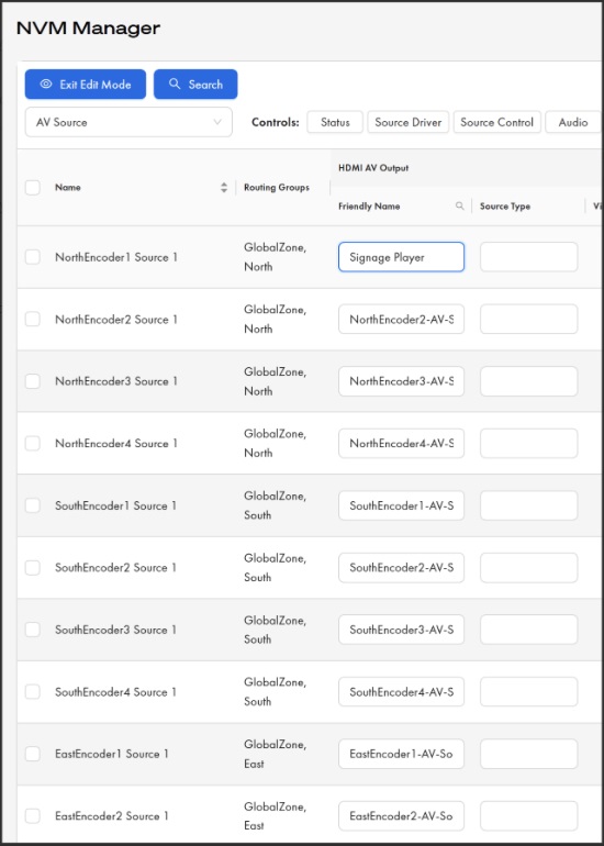
Figure 1. Encoders tab — editing AV Source Friendly Names.NVM Manager in Edit Mode showing the AV Source view with the HDMI AV Output > Friendly Name column active. The first row has been edited from the default name ("NorthEncoder1-AV-S…") to a descriptive Friendly Name ("Signage Player"). Use this column to assign meaningful names that appear in NVM Proxy device selector lists and throughout the system.
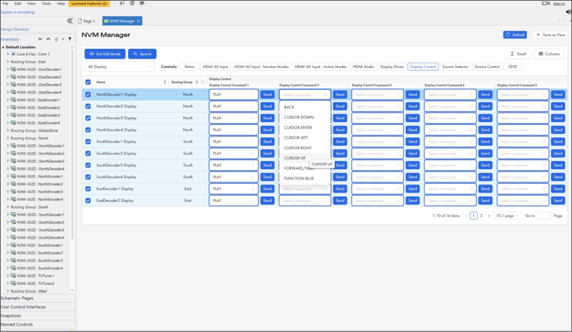
Figure 2. Decoders tab — assigning Display Control commands. NVM Manager in Edit Mode with the AV Display view, Display Control sub-section selected. The Display Control Command 2 drop-down is open, showing available commands from the loaded display driver (BACK, CURSOR DOWN, CURSOR ENTER, CURSOR LEFT, CURSOR RIGHT, CURSOR UP, FORWARD / NEXT, FUNCTION BLUE). Click Send to issue the assigned command to the display.
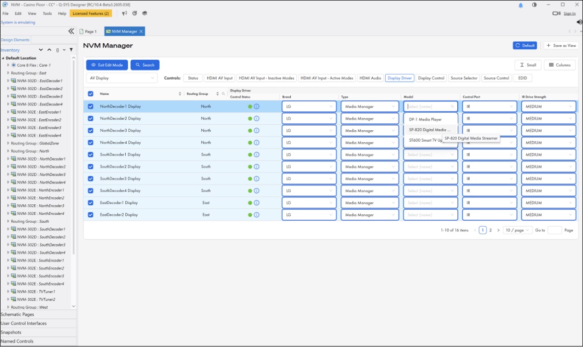
Figure 3. Decoders tab — configuring Display Drivers. NVM Manager in Edit Mode with the AV Display view, Display Driver sub-section selected. The Model drop-down for NorthDecoder2 Display is open, showing available models (DP-1 Media Player, SP-820 Digital Media…, ST600 Smart TV Up…) for the selected Brand (LG) and Type (Media Manager). The Control Status indicator (green) confirms the control connection is active. Configure Brand, Type, Model, Control Port, and IR Drive Strength to enable Q-SYS to control the physical display.
Cell Interaction
Cells in the NVM Manager table are interactive and their behavior depends on the control type.
| Control Type | Cell Behavior |
|---|---|
|
Text field (e.g., Friendly Name) |
Click the cell to enter text directly. Changes are applied when you press Enter or click away. |
|
Dropdown (e.g., Source Select by Name, EDID Mode, HDR Mode) |
Click the cell to open a dropdown list of available options. Select an option to apply it. |
|
Button (e.g., Save EDID, Command Send) |
Click the cell to trigger the button action. Momentary buttons activate on click and release automatically. |
|
Toggle / Switch (e.g., Mute, Streaming Enable) |
Click the cell to toggle the value between on and off. |
|
Fader (e.g., Gain) |
Click and drag within the cell to adjust the value, or click to enter a numeric value directly. |
|
LED indicator (e.g., Status, Source Active) |
Read-only. Displays the current state with color coding (green = OK, yellow = compromised, red = fault. |
|
Audio level meter |
Read-only. Displays real-time audio levels. Meters show the incoming audio signal and are not affected by mute or gain settings. |
|
Media display / Preview |
Read-only. Displays a 1 fps preview image of the source content (for sources that support previews). |
Note: Some controls in NVM Manager are proxied from other devices. For example, the AV Display's Source Selector controls are proxied from the AV Source component. These proxied controls appear in the table under the device that exposes them to the user and do not need to be accessed separately.
Table Features
Sorting
Click any column header to sort all rows by that column's values. The first click sorts A–Z (ascending); the second click sorts Z–A (descending). A sort indicator (triangle/arrow) appears on the column header currently being sorted. Only one column can be sorted at a time — sorting a new column removes the sort from the previous one.
When the table is grouped by Routing Group or Room Combiner, sorting a column within one group applies the same sort to all groups.
Grouping
The Group by option at the top of the table allows you to organize devices into logical groupings
| Group By | Description |
|---|---|
|
Device (default) |
Groups devices by type — all Encoders together, all Decoders together, all Routing Groups together. Shows properties for all devices. |
|
Routing Group |
Groups devices by Routing Group, then by type within each group. Shows Routing Group properties at the top of each group, followed by the Encoders and Decoders assigned to that group. |
|
Room Combiner |
Groups devices by Room Combiner, then sub-groups by Routing Group and type. Shows Room Combiner properties at the top of each combiner group. |
|
Proxy |
Shows only NVM Proxy data. |
Search and Filter
The search bar at the top of the table allows you to find devices or device properties by matching a text string. As you type, suggestions appear with tags identifying which property matched, so you can filter on exactly what you need. The table filters in real time as you type.
Filters can be combined with grouping and sorting to create highly focused views of your system.
Column Management
Columns can be customized to show only the controls relevant to your current task.
-
Show / Hide columns — Use the column selector to check or uncheck individual columns. Different column options are available depending on the device type you are viewing.
-
Reorder columns — Drag column headers left or right to rearrange them in any order.
-
Resize columns — Drag the border between column headers to adjust column width.
Row Height
Row height can be adjusted to accommodate controls that benefit from more vertical space, such as audio level meters or preview images.
Expandable Sections
Device categories and subcomponent groups can be expanded or collapsed. For example, within the Decoders tab, you can expand or collapse the AV Display, Source Control, Audio, and EDID sections to focus on the controls you need.
Pagination
For large designs with many devices, the table is paginated. The page size and current page are displayed at the bottom of the table, allowing you to navigate through the full device list.
Device Selection
You can select one or more device rows using the row checkboxes. When devices are selected, the interface displays the count of selected devices. Selection is useful for bulk operations and for identifying which devices you are working with.
Views
NVM Manager supports views, which allow you to save a specific table configuration as a named view that can be recalled at any time.
Default View
The Default view is a pre-set view that comes out of the box. It provides a standard starting configuration. The Default view always resets back to its original configuration and cannot be permanently modified — any changes you make while the Default view is active are temporary and revert when you switch away.
Custom Views
Custom views are user-created views that save your preferred table configuration. You can create multiple custom views for different tasks.
To create a custom view, configure the table the way you want it, grouping, visible columns, column order, column widths, expanded sections, then click Add View and give it a name. The view appears as a tab across the top of the NVM Manager window for quick access.
Custom views support the following operations.
| Operation | Description |
|---|---|
|
Save |
Opens a modal with the text "Save changes to view:" and checkboxes for the aspects you want to save: Expanded Device Categories, Visible Columns, Column Order, and Column Widths. All are checked by default. Uncheck any you don't want to overwrite. |
|
Rename |
Opens a modal with a text field where you can change the name of the view. |
|
Delete |
Opens a confirmation modal: "Are you sure you want to delete this view?" |
Note: When you edit columns, filters, or other table settings, changes are not automatically saved to the current view. You must explicitly select Save to persist your changes. This prevents accidental overwrites.To rename or delete a view, click on the view's name tab and select the desired option from the menu.
Reset All Views
Accessed from the settings gear icon, Reset All Views resets all views, including custom views, back to their default state.
Example Views
Custom views can be tailored to common tasks by showing only the columns relevant to that workflow.
| View | Controls to Include |
|---|---|
|
Network |
Mediacast streaming controls—RTP addresses, bitrates, streaming modes, video formats. |
|
Source & Display |
Friendly Names, Source Selectors, driver configurations, EDID settings. |
|
Audio |
Gain faders, mute buttons, audio level meters. |
|
Status |
Device status LEDs, HDMI connection status, HDCP status, HDR status. |
The controls available in NVM Manager mirror the controls found on each NVM component's control panel in Q-SYS Designer. The following sections detail every control group available for each device type.
NVM Encoder Controls
Status
| Control | Type | Description |
|---|---|---|
|
Encoder Status |
LED |
Device status indicator. Shows OK, Compromised, Fault, Not Present, Missing, or Initializing. |
Encoder
| Control | Type | Description |
|---|---|---|
|
Encoder Mode |
Drop-down |
Selects the Encoder's operating mode (e.g., 1×1, 2×1). Determines how many AV Sources and Mediacast outputs the Encoder supports. |
AV Source - Video
| Control | Type | Description |
|---|---|---|
|
Source Input Format |
Text Display |
Read-only. Shows the detected input video format from the connected source. |
|
HDMI 5V Status |
LED |
Read-only. Indicates whether the HDMI source is providing 5V (i.e., a source is connected and powered). |
|
HDCP Mode |
Drop-down |
Sets the HDCP behavior for the source input. |
|
HDCP Status |
Text Display |
Read-only. Shows the current HDCP authentication status. |
AV Source - Audio
| Control | Type | Description |
|---|---|---|
|
Channel n Gain |
Fader |
Per-channel gain control for the AV Source's embedded audio. |
|
Channel n Mute |
Toggle |
Per-channel mute. |
|
Channel n Invert |
Toggle |
Per-channel polarity invert. |
|
Channel n Level |
Meter |
Per-channel audio level meter. Shows incoming audio before gain / mute stages. |
|
Channel n Valid |
LED |
Per-channel indicator showing whether embedded audio is present on this channel. |
AV Source - Control
| Control | Type | Description |
|---|---|---|
|
Brand |
Drop-down |
Selects the brand of the source device for driver assignment. |
|
Type |
Drop-down |
Selects the device type within the selected brand. |
|
Model |
Drop-down |
Selects the specific model within the selected type. |
|
Control Port |
Drop-down |
Selects the control port used to communicate with the source device (e.g., serial, IR, IP). |
|
IR Drive Strength |
Drop-down |
Sets the IR output drive strength when using IR control. |
|
IP Address |
Text Field |
IP address of the source device (when using IP control). |
|
Control Status |
Text Display |
Read-only. Shows the current status of the control connection to the source device. |
|
Driver Version |
Text Display |
Read-only. Shows the version of the currently loaded device driver. |
|
Reload Driver |
Button |
Reloads the device driver. Useful after updating driver files. |
AV Source — EDID
| Control | Type | Description |
|---|---|---|
|
EDID Mode |
Drop-down |
Selects the EDID mode for the source input. |
|
Save EDID |
Button |
Saves the current EDID to the Core. |
Mediacast — Main Stream
| Control | Type | Description |
|---|---|---|
|
Streaming |
Toggle |
Enables or disables the main Mediacast stream. |
|
RTP Address |
Text Field |
The RTP multicast address for the main stream. |
|
Max Bitrate |
Drop-down |
Sets the maximum encoding bitrate for the main stream. |
|
Streaming Mode |
Drop-down |
Selects the streaming mode. |
|
Format |
Drop-down |
Selects the video encoding format. |
|
Frame Rate |
Drop-down |
Selects the output frame rate. |
|
Video Format |
Drop-down |
Selects the output video format / resolution. |
Mediacast — Preview Stream
| Control | Type | Description |
|---|---|---|
|
Enable |
Toggle |
Enables or disables the preview stream. |
|
RTSP URL |
Text Display |
Read-only. Shows the RTSP URL for the preview stream. |
|
RTP Address |
Text Field |
The RTP multicast address for the preview stream. |
|
Max Bitrate |
Drop-down |
Sets the maximum encoding bitrate for the preview stream. |
|
Streaming Mode |
Drop-down |
Selects the streaming mode for the preview stream. |
|
Format |
Drop-down |
Selects the video encoding format for the preview stream. |
|
Frame Rate |
Drop-down |
Selects the output frame rate for the preview stream. |
|
Video Format |
Drop-down |
Selects the output video format / resolution for the preview stream. |
Note: Encoders configured with 2 Mediacast Outputs (NVM-E2 application mode) display a second set of Mediacast stream controls for the second output.
Note: The RTP addresses shown here are automatically assigned from the Video Endpoints multicast address range configured in Core Manager > Network > Multicast. If you need to change the multicast address range, you must restart your design for the new range to take effect. For details on multicast address capacity and range configuration, see Network > Multicast.
NVM Decoder Controls
Status
| Control | Type | Description |
|---|---|---|
|
Decoder Status |
LED |
Device status indicator. Shows OK, Compromised, Fault, Not Present, Missing, or Initializing. |
AV Display — Source
| Control | Type | Description |
|---|---|---|
|
Source Select by Name |
Drop-down |
Selects the source feeding this display from the device's Source Selector List (SSL). |
|
Source Active X |
LED |
Indicates whether source row X is active and has a valid input. |
|
Source Type |
Text Display |
Read-only. Shows the type designation of the currently selected source. |
|
Source Preview |
Media Display |
Read-only. Shows a 1 fps preview image of the current source. |
AV Display — HDMI AV Input
| Control | Type | Description |
|---|---|---|
|
Friendly Name |
Text Field |
The display's Friendly Name. Appears in NVM Proxy device selector lists and throughout the system. Defaults to the NVM device name. |
|
Display Type |
Text Field |
A user-defined text string identifying the type of display. Can be used by UCI Designers to conditionally show or hide control elements. |
|
Zone Name |
Text Display |
Read-only. Shows the name of the Routing Group the display's decoder is assigned to. Blank if not assigned. |
|
HDR Mode |
Drop-down |
Sets HDR behavior: Auto or Force SDR. |
|
HDR Status |
Text Display |
Read-only. Shows the current HDR status (e.g., "SDR 8-bit," "HDR10 10-bit," "HLG 10-bit"). |
AV Display — EDID
| Control | Type | Description |
|---|---|---|
|
EDID Name |
Text Display |
Read-only. EDID name reported by the connected display. |
|
EDID Serial Number |
Text Display |
Read-only. EDID serial number. |
|
EDID Audio Channels |
Text Display |
Read-only. Number of audio channels reported in the EDID. |
|
Save EDID |
Button |
Saves the current EDID. |
AV Display — Video
| Control | Type | Description |
|---|---|---|
|
Output Video Format |
Drop-down |
Sets the output video format / resolution sent to the display. |
|
Output Color Format |
Drop-down |
Sets the output color format. |
|
HDCP Mode |
Drop-down |
Sets the HDCP behavior for the display output. |
|
HDCP Status |
Text Display |
Read-only. Shows the current HDCP authentication status. |
|
HPD |
Button |
Triggers a Hot Plug Detect event on the HDMI output. |
|
Video Mute |
Toggle |
Mutes the video output (sends a black frame). |
|
Video Freeze |
Toggle |
Freezes the current video frame on the display. |
|
Inactive Mode |
Drop-down |
Sets the behavior when no active source is selected (e.g., black screen, last frame, test pattern). |
AV Display — Audio
| Control | Type | Description |
|---|---|---|
|
Channel n Gain |
Fader |
Per-channel gain for the display's HDMI audio output. |
|
Channel n Mute |
Toggle |
Per-channel mute. |
|
Channel n Invert |
Toggle |
Per-channel polarity invert. |
|
Channel n Level |
Meter |
Per-channel audio level meter. Shows incoming audio before gain / mute stages. |
|
Channel n Valid |
LED |
Per-channel indicator showing whether embedded audio is present. |
AV Display — Display Control
| Control | Type | Description |
|---|---|---|
|
Brand |
Drop-down |
Selects the brand of the display for driver assignment. |
|
Type |
Drop-down |
Selects the device type within the selected brand. |
|
Model |
Drop-down |
Selects the specific model. |
|
Control Port |
Drop-down |
Selects the control port used to communicate with the display. |
|
Command n Command |
Drop-down |
Assigns a display control command to row n. |
|
Command n Send |
Button |
Sends the display command assigned to row n. |
|
Current Command |
Text Display |
Read-only. Shows the command currently being sent (non-latching). |
|
Last Command |
Text Display |
Read-only. Shows the last command sent (latching). |
Source Control
| Control | Type | Description |
|---|---|---|
|
Command n Command |
Drop-down |
Assigns a source control command to row n. Commands are pulled from the driver of the currently selected source. |
|
Command n Send |
Button |
Sends the source command assigned to row n. Supports press-and-hold. |
|
Current Command |
Text Display |
Read-only. Currently active source command (non-latching). |
|
Last Command |
Text Display |
Read-only. Last source command sent (latching). |
|
Snapshot Command |
Text Field |
Source command triggered via Snapshot. |
Mediacast Inputs
| Control | Type | Description |
|---|---|---|
|
Use Friendly Name n |
Toggle |
When enabled, the Mediacast Input uses the Friendly Name instead of the default system name. |
|
Friendly Name n |
Text Field |
User-defined Friendly Name for Mediacast Input n. |
Status
| Control | Type | Description |
|---|---|---|
|
Routing Group Status |
LED |
Status indicator for the Routing Group. |
|
Graphics in Selector List |
Drop-down |
Controls whether Graphics sources appear in the Routing Group's Source Selector Lists. |
Audio Output
| Control | Type | Description |
|---|---|---|
|
Audio Output Select by Name |
Drop-down |
Selects which AV Display in the Routing Group provides the audio source. |
|
Zones Combined |
Text Display |
Read-only. Shows which Routing Groups are currently combined with this one. |
|
Link to Room Combiner |
Toggle |
Links the gain control bidirectionally between the Routing Group and the Room Combiner. |
|
Gain |
Fader |
Routing Group audio output gain. |
|
Mute |
Toggle |
Routing Group audio output mute. |
All Output
| Control | Type | Description |
|---|---|---|
|
Friendly Name |
Text Field |
Friendly Name for the Routing Group's All Outputs aggregate. |
Mediacast Inputs n
| Control | Type | Description |
|---|---|---|
|
Use Friendly Name n |
Toggle |
When enabled, the Mediacast Input uses the Friendly Name instead of the default system name. |
|
Friendly Name n |
Text Field |
User-defined Friendly Name for Mediacast Input n. |
Note: Where n represents the Mediacast Input number. The number of available Mediacast Inputs depends on the Routing Group's configuration.
Mediacast Output n
| Control | Type | Description |
|---|---|---|
|
Friendly Name |
Text Field |
Friendly Name for Mediacast Output n. |
|
Source Select by Name |
Drop-down |
Selects the source feeding this Mediacast Output. |
|
Source Type |
Text Display |
Read-only. Type designation of the currently selected source. |
|
Source Preview |
Media Display |
Read-only. 1 fps preview image of the current source. |
|
Source Active n |
LED |
Indicates whether source row n is active. |
|
Command n Command |
Drop-down |
Assigns a source control command to row n. |
|
Command n Send |
Button |
Sends the source command assigned to row n. |
|
Current Command |
Text Display |
Read-only. Currently active source command. |
|
Last Command |
Text Display |
Read-only. Last source command sent. |
|
Snapshot Command |
Text Field |
Source command triggered via Snapshot. |
Configuring a New NVM System
After building your NVM system structure in NVM Designer, adding Encoders, Decoders, Routing Groups, and Room Combiners, switch to NVM Manager to configure device controls.
Configuring Device Controls
-
Start Emulation. NVM Manager requires the Design to be running or emulating for controls to be editable. Start Emulation from Q-SYS Designer.
-
Open NVM Manager. Go to Tools > NVM > NVM Manager.
-
Assign Friendly Names. Navigate to the Decoders tab. Locate the Friendly Name column under AV Display > HDMI AV Input. Click each cell and enter a descriptive name for each display (e.g., "Lobby Display 1," "Conference Room A Left"). Repeat for Encoders AV Source Friendly Names and Routing Groups.
-
Configure Display Drivers. In the Decoders tab, locate the Display Control columns (Brand, Type, Model, Control Port). For each display, select the appropriate driver from the drop-downs. This enables NVM Manager and UCIs to send control commands (power on/off, input select, etc.) to the physical display.
-
Configure Source Drivers. In the Encoders tab, locate the AV Source > Control columns. Assign the appropriate source driver for each connected source device.
-
Set EDID and HDCP. Configure EDID modes and HDCP settings for each Encoder's AV Source inputs and each Decoder's AV Display outputs.
-
Configure Mediacast Streaming. In the Encoders tab, configure RTP addresses, bitrates, streaming modes, and video formats for each Encoder's Mediacast streams.
-
Set Audio Levels. Use the audio gain faders and mute controls to set initial audio levels for AV Sources and AV Displays.
Tip: Create a custom view for each step (e.g., a "Friendly Names" view showing only name columns, a "Drivers" view showing only driver columns) to reduce visual clutter and speed up configuration.
Debugging Audio Issues
Troubleshooting Audio Problems in a Running System
-
Open NVM Manager and create or select a view that shows audio controls: Gain, Mute, Invert, Level meters, and Valid indicators.
-
Group by Routing Group to see all devices within each group together.
-
Check the Valid LEDs. If a channel shows "not valid," the source is not providing embedded audio on that channel.
-
Check the Level meters. These show the raw incoming audio before gain and mute. If the meters show signal, but you hear nothing, check the Mute and Gain settings.
-
Trace the audio path: AV Source audio → Encoder → Decoder → AV Display audio → Routing Group audio output. Each stage has its own gain, mute, and level controls visible in NVM Manager.
Monitoring System Health
Ongoing System Monitoring
-
Open NVM Manager and select or create a "Status" view showing Status LEDs, HDMI 5V status, HDCP status, and HDR status columns.
-
Scan the Status LED column for any devices showing yellow (Compromised) or red (Fault) indicators.
-
Check HDMI 5V status on Encoders to verify all sources are connected and powered.
-
Check HDCP status on both Encoders and Decoders to verify content protection is authenticating correctly.
NVM Manager is a tool, not a schematic component. It does not have configurable properties in the Properties pane of Q-SYS Designer.
The NVM Manager tool itself does remember user preferences—selected device tab, row height, column settings, and active view—between sessions, so your custom table configuration persists across Designer restarts.
NVM Manager is a tool, not a schematic component. It does not have its own control panel.
Instead, NVM Manager displays the controls of every NVM Encoder, Decoder, and Routing Group in the Design. The controls shown in the NVM Manager table are the same controls documented in the individual NVM component help topics—NVM Encoder, NVM Decoder, NVM Routing Group. See the Device Controls in NVM Manager section above for a complete listing of every control exposed in the table.
NVM Manager does not have control pins. It is a management tool, not a schematic component.
To access NVM device controls programmatically via Lua scripting or external control protocols, use the control pin names documented in each NVM component's help topic—NVM Encoder, NVM Decoder, NVM Routing Group, NVM Proxy.