Encoder (NVM-302E)
The NVM‑302E Encoder is a subcomponent of the NVM‑302E that converts HDMI video and embedded audio into a Mediacast stream for network distribution. It accepts input from a source device — such as a PC, media player, or set‑top box — and publishes the stream so that any mediacast‑capable endpoint, most commonly an NVM‑302D decoder, can subscribe to it for display.
The NVM‑302E is typically used to:
-
Bring a local HDMI source onto the Q‑SYS network for distribution to one or many displays.
-
Build scalable video systems where sources can be routed without point‑to‑point wiring using Routing Groups.
-
Monitor and manage stream health—including streaming state, negotiated format, and network addressing—directly from Q‑SYS Designer or management tools.
Depending on configuration, the encoder can publish one or two Mediacast outputs:
-
Single‑output mode publishes one Mediacast stream (NVM-E1).
-
Dual‑output mode publishes two independent Mediacast streams, allowing simultaneous distribution of two inputs (NVM-E2, license required).
The Encoder provides controls for both the Mediacast main stream—the full‑quality stream delivered to decoders—and the Preview stream, a lower‑resolution version used for live thumbnails in UCIs, source selector buttons, and Mediacast Routers. Each Mediacast output includes both a main stream and a preview stream.
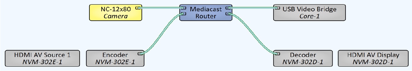
In Q‑SYS Designer, the NVM‑302E appears as an inventory device with related subcomponents, such as the Encoder and HDMI AV Source controls. The Encoder can be placed in the schematic to expose its Mediacast Output pins for manual wiring, but it does not need to be placed to function. When the NVM-302E is assigned to a Routing Group, the Encoder's Mediacast output is automatically available to all decoders in that group. This allows you to configure naming, stream behavior, and monitoring without requiring manual schematic wiring in every design.
The NVM-302E Encoder and NVM-302D Decoder are complementary components. The Encoder accepts HDMI sources and encodes them into Mediacast streams; the Decoder receives Mediacast streams and outputs them to HDMI displays. Key differences:
|
Encoder (NVM-302E) |
Decoder (NVM-302D) |
|
|---|---|---|
|
Role |
Encodes HDMI input into Mediacast IP streams. |
Decodes Mediacast IP streams to HDMI output. |
|
Subcomponents |
HDMI AV Source 1 (and optionally Source 2), Encoder, Status, Serial Ports, USB HID. |
HDMI AV Display, Decoder, Status, Serial Port, USB HID. |
|
Mediacast I/O |
Mediacast Output pins (1 or 2). |
Mediacast Input pins (set via Decoder properties). |
|
Application Modes |
NVM-E1 (1 output, up to 4K60) or NVM-E2 (2 outputs, up to 4K30 each). |
NVM-D1 (1 input). |
|
HDMI Input Config |
1×1 4K60 or 2×1 4K30 (NVM-E1 only). |
N/A. |
|
Source Selection |
Internal input selector (2×1 mode). |
Source Selection List (from Routing Group or wired sources). |
The NVM-302E supports two application modes:
-
NVM-E1 (default, no license required) — Single Mediacast output. Supports two HDMI input at up to 4K60, or two HDMI inputs pre-switched to a single Mediacast output stream at up to 4K60 (determined by the HDMI Input Config property). When two inputs are configured, the Encoder's control panel includes Input Select buttons to switch between them.
-
NVM-E2 (license required) — Two independent Mediacast output streams, each at up to 4K30. HDMI AV Source 1 always feeds Mediacast Output 1; HDMI AV Source 2 always feeds Mediacast Output 2. No internal input selector is needed.
Note: You can order the NVM-E2 as a bundle (NVM-302E + SLNVM-E2) or simply order the NVM-302E (NVM-E1) and upgrade it to an NVM-E2 later in the field via the SLNVM-E2.
Note: Each Mediacast output uses two multicast addresses — one for the main stream and one for the preview stream. In NVM-E1 mode, each encoder uses two multicast addresses. In NVM-E2 mode, each encoder uses four. These addresses are drawn from the Video Endpoints multicast address range configured in Core Manager > Network > Multicast. The default range supports up to 256 multicast streams per Core. If your design approaches this limit, use Manual mode in Core Manager to specify a wider range. For more information, see Network > Multicast.
Each Mediacast output includes a Preview stream — a lower-resolution (up to 360p30) encoded stream plus a 1fps JPEG thumbnail. Preview streams are used for:
-
Live video preview thumbnails on source selector buttons (in AV Displays, Routing Groups, NVM Proxy, and Mediacast Routers).
-
Media Display components dragged into UCIs for live monitoring.
The Preview stream is independent of the main stream and can be enabled or disabled separately. When disabled, UCIs fall back to the 1fps JPEG thumbnail.
Input Pins
The Encoder component has no input pins. HDMI sources connect to the NVM-302E's HDMI AV Source subcomponents, which feed the Encoder internally.
Output Pins
| Pin | Description |
|---|---|
|
IP Stream 1 |
Mediacast output for the first encoded stream. Always present. Connect to a Routing Group Mediacast input, Mediacast Router input, or any compatible Mediacast input pins. |
|
IP Stream 2 |
Mediacast output for the second encoded stream. Only present when the Application property is set to NVM-E2. |
NVM-302E Properties
Properties are displayed in the right-side pane of Q-SYS Designer when the Encoder component is selected. The Properties pane shows both the parent NVM-302E properties and the HDMI AV Source properties.
Name
The Name may contain ASCII letters 'a' through 'z' (case-insensitive), the digits '0' through '9', and the hyphen. Names cannot begin or end with a hyphen. No other symbols, punctuation characters, or blank spaces are permitted. Options: Text. Default: auto-assigned.
Location
User-defined name that groups the component with other components in the same physical location, for example, "Casino West". Options: Text. Default: blank.
Is Required
Sets whether the NVM-302E is required for the design to report OK status. When enabled, and the device is not found on the network, the device is reported as 'Missing', which is an error condition. This is the default behavior. When disabled, and the device is not found on the network, the device is reported as 'Not Present', which is not an error condition. Options: Yes. No. Default: Yes.
Dynamically Paired
Indicates that this virtual component can be paired with the same type of hardware without changing the network ID of the hardware or the name of this component. Refer to the Q-SYS Core Manager Dynamic Pairing topic for more information. The default is 'No'.
External USB Audio
When enabled, you can connect an external audio device to the USB input and route audio to and from that device. See External USB Audio Device In and External USB Audio Device Out.
Routing Groups
Routing Groups are named video zones that link NVM Encoders and Decoders so they can route sources to displays without manual Mediacast wiring. Assigning an encoder to a Routing Group makes its HDMI input(s) available as sources in that group, and assigning a decoder to the same group lets its displays see and select those sources by name.
Application
Sets the application mode for the NVM-302E. NVM-E1 provides a single Mediacast output at up to 4K60 (no license required). NVM-E2 provides two independent Mediacast outputs at up to 4K30 each (license required). Changing this property changes the number of HDMI AV Source subcomponents and Mediacast Output pins. Options: NVM-E1, NVM-E2. Default: NVM-E1.
HDMI Input Config
Sets the HDMI input configuration when Application is NVM-E1. 1×1 4K60 uses a single HDMI input at up to 4K60. 2×1 4K30 uses two HDMI inputs pre-switched to a single Mediacast output at up to 4K30; the Encoder's control panel includes Input Select buttons to switch between them. This property is not available when Application is NVM-E2. Options: 1×1 4K60, 2×1 4K30. Default: 1×1 4K60.
HDMI AV Source Properties
Note: The following properties belong to the HDMI AV Source subcomponent. For full HDMI AV control and control pin documentation, see HDMI AV Source (NVM-302E).
Is Required
Sets whether this AV Source subcomponent is required for the design to report OK status. Options: Yes, No. Default: No.
Audio Channels
Sets the number of audio channels for HDMI embedded audio. This determines how much embedded audio travels with the video in the Mediacast output stream to NVM‑302D decoders and other Mediacast receivers. Setting the value to 0 produces a video‑only stream and disables Breakaway Audio. LPCM only (32 kHz–48 kHz). One audio channel is not a valid setting. Options: 0, 2–8. Default: 2.
Breakaway Audio
When enabled, the HDMI embedded audio is separated from the video stream and routed to dedicated Breakaway Audio output pins for independent processing. The video continues on its normal path. The number of audio pins is determined by the Audio Channels property. Disabled (grayed out) when Audio Channels is set to 0. USB‑C AV connections do not support Breakaway Audio. Options: Disabled, Enabled. Default: Disabled.
Video Format Error
Controls how the component reports fault status when the connected HDMI source is sending a video format that cannot be processed, such as an incompatible resolution, frame rate, or interlaced signal. Options: Fault – Unsupported, Fault – Unsupported / No Format, Ignore. Default: Fault – Unsupported.
-
Fault – Unsupported (default) — Reports a Fault for unsupported or interlaced video formats. Ignores no-signal conditions (no fault when nothing is connected).
-
Fault – Unsupported / No Format — Reports a Fault for unsupported formats, interlaced formats, and when no video format is detected (no signal).
-
Ignore — Ignores all HDMI source faults. Component status shows OK regardless of video format.
Audio Source
Selects where the AV output obtains its audio. Source uses the embedded HDMI audio from the connected device. Audio Breakin Pins replaces the HDMI audio with external audio routed through the component's Breakin pins, which become visible when this option is selected. Each HDMI AV Source can choose its audio source independently. Hidden or disabled when Audio Channels is set to 0. Options: Source, Audio Breakin Pins. Default: Source.
Source Control Count
Sets the number of source control command rows on the Control tab. Each row provides a command button that sends high-level commands — such as channel changes, navigation inputs, or power toggles — to the connected source device through the assigned device driver. Increasing the count exposes more commands; decreasing it hides them. Options: Integer, 0–64.
Graphic Properties
Label
User-defined text that appears next to the component on the Schematic. Changing the label does not affect the component name or system behavior.
Position
Specifies the X and Y coordinates of the component on the Schematic. The values update automatically when you move the component, and can be edited to place the component at an exact location.
Fill
Sets the background color of the component block on the Schematic. This is for visual organization only and does not affect system operation.
Script Access Properties
Code Name
Displays the currently assigned name for control access. You can use the auto-assigned name or customize it. Q-SYS will automatically check all Code Names in the design to ensure name is unique.
Script Access
Defines whether the component will be accessible by script and/or externally, or not at all. Choices include All, External, None (default), and Script.
- None (default) - Not accessible by any script, plugin, or by Q-SYS Remote Control Protocol (QRC).
- Script - Can be accessed by scripts, such as Text Controller, Block Controllers, and plugins only.
- External - Can only be accessed by 3rd party controls systems using component commands from the Q-SYS Remote Control Protocol (QRC).
- All - No restrictions, can be accessed by 3rd party control systems via Q-SYS Remote Control Protocol (QRC), or script objects or plugin objects.
Tip: Use Script Programmer Mode to quickly view the Script Access setting directly on the component in the design schematic without the need to disconnect from the Q-SYS Core processor.
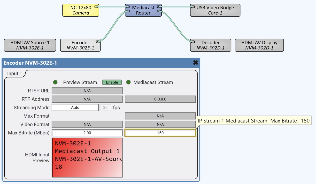
The Encoder control panel shows the IP Stream controls for each Mediacast output. When the Application is NVM-E2 or HDMI Input Config is 2×1 4K30, the control panel expands to show controls for each input / output.
Input n (per Mediacast Output)
Preview Stream
| Control | Type | Description |
|---|---|---|
|
Preview Stream LED |
LED |
Device status indicator. Shows OK, Compromised, Fault, Not Present, Missing, or Initializing. |
|
Status |
Text |
Displays the current status: OK, Initializing, Compromised, Missing, Fault, Unknown, or Not Present. |
|
RTSP URL |
Text (read-only) |
Displays the RTSP URL for the Preview stream when enabled. |
|
RTP Address |
Text (read-only) |
Displays the multicast RTP address assigned to the Preview stream when enabled. This address comes from Core Manager's Multicast Address range for Cameras. Note: This address is assigned from the multicast range configured in Core Manager. If you change multicast address ranges, you must restart your design. |
|
Streaming Mode |
Drop-down + fps |
When set to Auto, the resolution and frame rate are automatically adjusted. When a manual resolution is selected (e.g., h.264 640H), you can choose an fps value from 1 to 30. |
|
Max Format |
Text (read-only) |
Displays the maximum video format for the Preview stream. |
|
Video Format |
Text (read-only) |
Displays the current, actively streaming format of the Preview stream. |
|
Max Bitrate (Mbps) |
Fader |
Sets the maximum average bitrate for the Preview stream, from 0.5 to 2.0 Mbps. Instantaneous bitrate can exceed this value up to network limitations. |
|
HDMI Input Preview |
Preview Window |
Displays a live video preview of the HDMI input. Can be dragged into a UCI to create a Media Display. |
Mediacast Stream
| Control | Type | Description |
|---|---|---|
|
Mediacast Stream LED |
LED (green) |
Glows green when the Mediacast main stream is actively streaming on the network. |
|
Streaming |
LED |
Indicates that the main Mediacast stream is actively being transmitted. |
Input Select (NVM-E1 with 2×1 4K30 only)
These controls only appear when Application is NVM-E1 and HDMI Input Config is 2×1 4K30.
| Control | Type | Description |
|---|---|---|
|
Input Select 1 |
Toggle |
When on, HDMI AV Source 1 is selected as the source for Mediacast Output 1. Pressing this button turns off Input Select 2. |
|
Input Select 2 |
Toggle |
When on, HDMI AV Source 2 is selected as the source for Mediacast Output 1. Pressing this button turns off Input Select 1. |
The control pin tree is organized under IP Stream 1 (and IP Stream 2 when Application is NVM-E2).
IP Stream n — Mediacast Stream
| Pin Name | Control Type |
Value |
String | Position |
Direction |
Description |
|---|---|---|---|---|---|---|
|
Streaming |
LED |
0 1 |
false true |
0 1 |
Output |
Mediacast main stream is actively streaming. |
P Stream n — Preview Stream
| Pin Name | Control Type | Value | String | Position | Direction | Description |
|---|---|---|---|---|---|---|
|
Enable |
Button |
0 1 |
false true |
0 1 |
Input / Output |
Enable or disable the Preview stream. |
|
Max Bitrate |
Fader |
0.5–2.0 | 0.5Mbps to 2.0Mbps |
0.000 to 1.00 |
Input / Output |
Maximum average bitrate for the Preview stream. |
|
Max Format |
Text |
— |
text |
— |
Output |
Maximum video format for the Preview stream. |
|
RTP Address |
Text |
— |
text |
— |
Output |
Multicast RTP address for the Preview stream. |
|
RTSP URL |
Text |
— |
text |
— |
Output |
Preview stream is actively streaming. |
|
Streaming Mode Format |
Selector |
— |
Auto, h.264 640H, h.264 320H |
— |
Input / Output |
Preview stream resolution mode. |
|
Streaming Mode Frame Rate |
Integer |
1–30 |
— |
— |
Input / Output |
Preview stream frame rate (fps). Disabled when Streaming Mode is Auto. |
|
Video Format |
Text |
— |
text |
— |
Output |
Current Preview stream format. |