QIO-GP8x8
The Q-SYS QIO-GP8x8 expands your Q-SYS system’s capabilities to enable streamlined interoperability with non-networked control devices via GPIO connectivity. By separating local I/O from processing hardware, the QIO Series offer modular and easily scalable network I/O to support your desired topology.
Note: This topic provides an overview of the QIO-GP8x8. For specifications and installation documentation, see the QIO-GP8x8 product page on the QSC website.
-
Native control I/O expander for Q-SYS
-
Eight (8) logic inputs and eight (8) logic outputs
-
Power-over-Ethernet capable
-
Daisy-chain up to four QIO network I/O expanders on a single network run (with local daisy-chained DC power)
-
Simple drag-and-drop integration and comprehensive management via Q-SYS Designer Software and Q-SYS Reflect Enterprise Manager
-
Surface- or rack-mountable
-
Includes surface mounting hardware
-
QIO-RMK rack mounting kit sold separately
-
QIO-PSU DC power supply sold separately
These Inventory components are available for the QIO-ML4i:
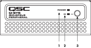
Front Panel

-
Power LED – Illuminates blue when the Q-SYS GP8x8 is powered on
-
ID LED – LED blinks green when placed into ID Mode via ID Button or Q-SYS Designer Software
-
ID Button – Locates the GP8x8 in Q-SYS Designer Software.
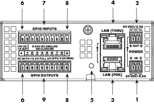
Rear Panel

-
External Power Input 24V DC 2.5 A – Auxiliary power, 24 VDC, 2.5 A, 2-pin Euro connector.
-
Daisy-Chain Power Output 24V DC 2.5 A – Auxiliary power, 24 VDC, 2.5 A 2-pin Euro connector.
-
LAN [PoE] – RJ-45 connector, PoE Type 1 Class 3, Q-LAN.
-
LAN [THRU] – RJ-45 connector, Ethernet daisy-chaining.
-
Device Reset – Use a paperclip or similar tool to restore default network settings and recover factory default settings. Before attempting a reset, refer to the Device Reset section for details.
-
12V DC .1A Out – For use with General Purpose Inputs and Outputs (GPIO). Uses black connector pins 1 and 11 (not numbered).
-
GPIO Inputs – 8 inputs, 0-24V analog input, digital input, or contact closure (Pins labeled 1–8 equal pins 1–8 in the Q-SYS Designer Software GPIO In (QIO-GP8x8) component). Configurable pull-up to +12V.
-
Signal Ground – For use with GPIO. Uses black connector pins 10 and 20 (not numbered).
-
GPIO Outputs – 8 outputs, open collector (24V, 0.2A sink maximum) with pull-up to +3.3V (Pins labeled 1–8 equal pins 1–8 in the Q-SYS Designer Software GPIO Out (QIO-GP8x8) component).
Product specifications and dimension drawings for the QIO-GP8x8 can be found on the QIO-GP8x8 product page.
You can perform either a short reset or long reset:
- Use a Short Reset to restore connectivity to a device in the event that unintended network settings were specified in Q-SYS Peripheral Manager or the device is otherwise unreachable. A short reset will restore device IP settings back to Auto mode (DHCP) and delete all Static Routes. The configured hostname is retained.
- Use a Long Reset to restore the device to factory condition. This is useful for deeper troubleshooting, or when preparing the device for decommissioning or transfer.
CAUTION: A Long Reset clears all network settings (including hostname), disables 802.1x, deletes user-installed device certificates, deletes all logs, and clears the device password.
Performing a Short Reset
- Press and hold the Reset Button until the Status LED (NL, NM Series) or Power LED (QIO Series) begins flashing blue slowly – approximately 10 seconds.
- Release the button before 20 seconds elapse.
- The device performs its prescribed Short Reset and reboots.
Note: To cancel the Short Reset, release the button before 10 seconds has elapsed.
Performing a Long Reset
- Press and hold the Reset Button until the Status LED (NL, NM Series) or Power LED (QIO Series) begins flashing blue rapidly – approximately 20 seconds.
- Release the button when the LED begins flashing rapidly.
- Within 30 seconds, press the Reset Button again to confirm the reset.
- The device performs its prescribed Long Reset and reboots.
Note: To cancel the Long Reset, do not press the Reset Button again during the 30 second confirmation period.
