Serial Port (QIO Series)
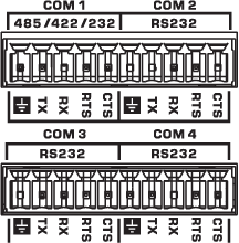
The QIO-S4 includes four serial ports for extension of Q-SYS Control to third-party devices, such as projectors, TVs, and A/V receivers. You can control and read from these devices using Lua script from a Q-SYS scripting component.
Tip: To learn about scripting in Q-SYS, see Control Scripting.
The QIO-S4 features four serial ports:
-
COM 1 is configurable in the QIO-S4 Serial Port 1 inventory component Properties for RS232, RS485 Half Duplex TX, RS485 Half Duplex RX, or RS485/422 Full Duplex.
-
COM 2-4 ports are dedicated to RS232 communication.

RS232 Pinout: COM 1 (Configurable), COM 2-4 (Dedicated)
| Pin | Signal Flow | Description |
|---|---|---|

|
N/A | Signal ground |
| TX | Output | Transmit data |
| RX | Input | Receive data |
| RTS | Output | Ready to Send1 |
| CTS | Input | Clear to Send1 |
1. When using hardware flow control.
RS485 Half Duplex TX or RX Pinout: COM 1 (Configurable)
| Pin | Signal Flow | Description |
|---|---|---|

|
N/A | Signal ground |
| TX | Input/Output | Differential B- |
| RX | (Unused) | (Unused) |
| RTS | Input/Output | Differential A+ |
| CTS | (Unused) | (Unused) |
RS485/422 Full Duplex: COM 1 (Configurable)
| Pin | Signal Flow | Description |
|---|---|---|

|
N/A | Signal ground |
| TX | Output | Differential Z- / Tx- |
| RX | Input | Differential A+ / Rx+ |
| RTS | Output | Differential Y+ / Tx+ |
| CTS | Input | Differential B- / Rx- |
Input Pins
This component has no input pins.
Output Pins
Serial Port 
Connect this pin to the Serial Input pin of a Q-SYS scripting component, such as Block Controller, Text Controller, or Control Script. You must configure these components for serial communication.
Name
The Name may contain ASCII letters 'a' through 'z' (case-insensitive), the digits '0' through '9', and the hyphen. Names cannot begin or end with a hyphen. No other symbols, punctuation characters, or blank spaces are permitted.
Location
User-defined name that groups the component with other components in the same physical location, or in the same organizational scheme.
Is Required
When enabled, and the device is not found on the network, the device is reported as 'Missing', which is an error condition. This is the default behavior. When disabled, and the device is not found on the network, the device is reported as 'Not Present', which is not an error condition.
Dynamically Paired
Indicates that this virtual component can be paired with the same type of hardware without changing the network ID of the hardware or the name of this component. Refer to the Q-SYS Core Manager Dynamic Pairing topic for more information. The default is 'No'.
Com Mode
(COM1 / Serial Port 1 only) Select the type of serial communication: RS232 (default), RS485 Half TX, RS485 Half RX, or RS485/422 Full. See the QIO-S4 Serial Port Pinouts section for more information.
Flow Control
Select whether to enable or disable flow control on the serial port. The default is Disabled.
TX Bytes
Displays a running total of the number of transmitted bytes of data.
RX Bytes
Displays a running total of the number of received bytes of data.
Reset
Click to reset the TX Bytes and RX Bytes counters to zero.
|
Pin Name |
Value |
String |
Position |
Pins Available |
|---|---|---|---|---|
|
Receive Bytes |
(text) |
Output |
||
|
Reset |
(trigger) |
Input/Output |
||
|
Transmit Bytes |
(text) |
Output |
||
Checking Pinouts
Check the pinout of any equipment, including the cable, to be connected to a Q-SYS serial port for input or output. In many cases, you can solve serial communication problems by inserting a null modem adapter or cable to swap the TX and RX pin positions. The TX pin on one end must be connected to an RX pin on the other end (and vice versa) for data to flow properly.
Proper RS-485/RS-422 Termination
To avoid communication errors with RS-485/RS-422 modes, you must match the terminating resistor's impedance to that of the cable being used. For example, if you are using a 120 Ohm cable, terminate both ends with a 120 Ohm resistor.
