Control Delay
The Control Delay provides the capability of delaying control signals from 0 milliseconds to 60 seconds. There is one input and up to 32 outputs available.
Note: The output behavior of Control Delay (all outputs) is determined by the first connected component wired to Output 1. For example, if Output 1 feeds a momentary or toggle pin of a connected component, Control Delay treats all downstream outputs for Output 1 – as well as Outputs 2-32 – as Boolean. If Output 1 feeds a trigger pin of a connected component, Control Delay treats all outputs as trigger.
Inputs and Outputs
Control components do not have traditional input and output pins. If a Control Pin is available for the component, an input or output will appear.
Control Pins represent the controls available in the component's Control Panel. Control Pins are used to link controls between Schematic Elements, and link to / from Control Scripts. Control Pin signal pins are represented by a  square, and the wiring is represented by a thick blue / white line.
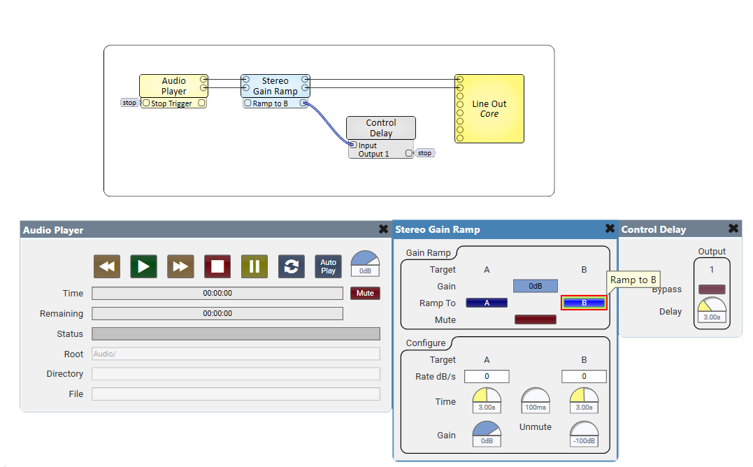
In this example, we are using a Gain Ramp Component to fade out theAudio Player and then use the Control Delay to Stop the Audio Player three seconds later to reset its file.
Tip: For additional properties that are not listed, refer to the Properties Panel help topic for more information.
Control Delay Properties
Output Count
Sets the number of outputs available, from 1 to 32 (default is 1).
Max Delay
Sets the maximum amount of delay, from 1 to 60 seconds (default is 10), that can be applied from the control panel.
Bypass
Bypasses the delay function for the associated channel. The Output is not delayed from Input.
Delay
Sets the delay time, from 0ms to 60.0s (default is 10.0s), from the Input to the Output. The maximum amount for all of the Delay channels is controlled by the Max Delay property.
Note: Entering anything from 0.001µs to 0.005µs gets interpreted as 1.00 through 5.00 milliseconds. Entering anything greater than 0.005 gets interpreted as the milliseconds as entered (example 0.006 gets interpreted as .006 ms). The basic idea is that the value that you enter is larger than the max value and Q-SYS Designer assumes you want the value to be divided by 1000. If you need to input less than 6ms, you must manually type in ("5us", "4us", etc.). You will then see it convert to .005 ms, .004ms, etc.
|
Pin Name |
Value |
String |
Position |
Pins Available |
|---|---|---|---|---|
|
Bypass |
0 1 |
no bypassed |
0 1 |
Input / Output |
|
Delay |
0.00 to 60.0 |
0ms to 60.0s |
0.000 to 1.00 |
Input / Output |