Core 110f
The Q-SYS™ Core 110f processor provides a fully integrated audio, video and control solution for installations with a mixture of analog and network channels, supporting medium-sized rooms through the largest Enterprise scale deployments.
Note: Q-SYS Core 110f units with 2 GB of RAM, manufactured before April 2017, are no longer supported in Q-SYS Designer v10.0 or later. However, some units may have had their motherboards replaced, resulting in 4 or 8 GB of RAM. Despite their earlier manufacturing dates, these upgraded units are supported in Q-SYS Designer v10.0 and later.
| Feature | Core 110f |
|---|---|
|
Total network I/O |
128 x 1281 |
|
Onboard I/O |
8x in, 8x out, 8x flex |
|
Software-based Dante capacity |
8 x 8 included (up to 32 x 32) |
|
USB audio channel count |
16 x 16 |
|
AEC processors |
16 |
|
VoIP instances |
4 |
|
Onboard AV bridging (USB) |
Yes |
|
Onboard GPIO |
Core 110f: 16 x 16 Core 110f v2: N/A |
|
Onboard RS232 control ports |
1 |
|
Maximum NV Series Network Video Endpoints |
32 |
|
Maximum NL, NM, and QIO Series Endpoints |
32 |
|
Size |
1RU |
1. When using the Core 110f on-board USB Device Port for video bridging, the Q-LAN / AES67 maximum audio channel count is 80 x 64 (Q-SYS version 9.7 and later) or 64 x 64 (Q-SYS version 9.6 and earlier).
The Core 110f is configurable in Core Mode or Peripheral Mode. By default, the Core 110f ships from the factory in Core Mode. It's easy to switch modes.
- Open Core Manager for the Core 110f.
- From the Utilities menu, change the Mode property to 'Peripheral'.
- Click Switch.
Once the device reboots, you can then configure it using Configurator > Peripheral Manager. In your design, add the I/O-Core 110f to your design from the Inventory > Audio - Q-LAN menu. Once you save and run your design to the Core, the I/O-Core 110f will then be functional as a peripheral after its firmware updates.
- From Configurator (Tools > Show Configurator), locate the I/O-Core 110f from the I/O Devices category.
- Click the device to open Peripheral Manager.
- From the Utilities tab, change the Mode property to 'Core'.
- Click Switch.
Once the device reboots, you can then configure it using Core Manager. In your design, be sure to change Core Properties > Model to 'Core 110f'. Once you save and run your design to the Core, the Core 110f will then be functional as a Q-SYS Core processor after its firmware updates.
Available Inventory components depend on whether the Core 110f is configured for Core Mode or Peripheral Mode.
Core Mode allows the Q-SYS Core processor to operate as a standalone audio and control processing unit. In Core Mode, this Q-SYS Core functions independently without relying on an external Q-SYS system or design file.
Standard Components
- Status (Core)
- Mic/Line In (Core 110f, 110c)
- Flex In (Core 110f, 110c)
- Line Out (Core 110f, 110c)
- Flex Out (Core 110f, 110c)
- POTS In
- POTS Out
- POTS Controller
- GPIO In (Core 110f, I/O-Core 110f, Core 110c) – Not applicable to the Core 110f v2
- GPIO Out (Core 110f, I/O-Core 110f, Core 110c) – Not applicable to the Core 110f v2
- Serial Port (Core and I/O Devices)
- Loudspeaker Monitor
- HID Keyboard
- HID Media
- HID Conferencing
- USB Input
- USB Output
External USB Audio
USB Video Bridge
USB Audio Bridge
Peripheral Mode allows the Q-SYS Core processor to operate as a peripheral device in an AV network rather than the central processing unit. In this mode, this Core can serve as an input/output expander, handling audio and control signals, while the core processing tasks are offloaded to a separate Q-SYS Core processor.
Standard Components
- Status (I/O-Core 110f)
- Mic/Line In (I/O-Core 110f)
- Flex In (I/O-Core 110f)
- Line Out (I/O-Core 110f)
- Flex Out (I/O-Core 110f)
- POTS In (I/O-Core 110f)
- POTS Out (I/O-Core 110f)
- POTS Controller (I/O-Core 110f)
- GPIO In (Core 110f, I/O-Core 110f, Core 110c) – Not applicable to the Core 110f v2
- GPIO Out (Core 110f, I/O-Core 110f, Core 110c) – Not applicable to the Core 110f v2
- Serial Port (Core and I/O Devices)
- Loudspeaker Monitor
- HID Keyboard
- HID Media
- HID Conferencing
Note: USB Input and USB Output components are not supported in Peripheral Mode.
External USB Audio
USB Video Bridge
USB Audio Bridge
Front Panel – Core 110f

- OLED Display – displays information about the core's settings and status.
- Next button – cycles through the information pages
- ID button – locates the Core in Q-SYS Designer GUI and Configurator
- Power LED – illuminates blue when the Core is on
- USB Type A Host connectors (2)
Front Panel – Core 110f v2
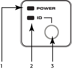
- Power LED – Illuminates blue when the Q-SYS Core 110 Series processor is powered on
- ID LED – LED blinks when placed into ID Mode via ID Button or Q-SYS Designer Software
- ID Button – Locates the Q-SYS Core 110 Series processor in Q-SYS Designer Software
Rear Panel — Left Side
All audio inputs and outputs use one 3-position, 3.5mm Euro connector for each channel. GPIO uses one 10-position 3.5mm Euro connector for each row. Configure all inputs and outputs in Q-SYS Designer.
Note: GPIO connections are not applicable to the Core 110f v2.

- Mic/Line Inputs – eight channels, balanced or unbalanced, phantom power – orange
- Flex Channels – eight user-configurable input/output channels, balanced or unbalanced, phantom power on inputs – blue
- Mic/Line Outputs – eight channels, balanced or unbalanced - green
The following connections use the black Euro plug and are not applicable to the Core 110f v2:
- 12VDC, 0.2A Outputs + uses connector pins 1 and 11 (not numbered)
- General-purpose Inputs – 16 inputs, 0-24V analog input, or contact closure (Pins labeled 1–16 equal pins 1–16 in the Q-SYS Designer GPIO Input component)
- Earth ground – uses pins 10 and 20 (not numbered)
- General-purpose Outputs – 16 outputs, open collector (24V, 0.2A maximum) with pull up to +3.3V (Pins labeled 1–16 equal pins 1–16 in the Q-SYS Designer GPIO Output component)
Rear Panel — Right Side

- Telephone Line – RJ11 (6P2C)
- Serial Number of the Core 110
- External Power Input – Auxiliary power, 12VDC, 10A, 2-pin, 5 mm Euro connector.
Note: Auxiliary power and AC power are parallel. They can be used simultaneously. If one source of power fails, it will "fail over" to the other power source without interruption.
- RS232 – Transmit and receive, 3-pin, 5 mm, Euro connector
- HDMI – for future use
- USB Type B Device connector
- LAN A – Q-LAN, control, VoIP, WAN streaming, AES67 etc., RJ45
- USB Type A Host connectors (4) for future use
- LAN-B – Redundancy, control, VoIP, etc.
- A/C Power Input – IEC connector, 100-240V ~ 50-60 Hz, 150W, universal power supply
Note: The front panel OLED is not applicable to the Core 110f v2.
Design Status
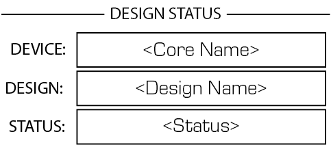
- Device – The name of the Core as defined in Q-SYS Designer.
- Design – The name of the currently running design.
- Status –
- OK – Audio is good, hardware is good.
- Compromised – Audio is good but a redundancy mechanism is active (one LAN down but the other is still up) or a non-fatal hardware problem exists (fans too slow, temperature higher than expected, etc.)
- Fault – Audio is not passing, or hardware is malfunctioning or mis-configured
- Missing – A piece of hardware, defined in the design, has not been discovered. Audio is not passing through that piece of hardware.
- Initializing – Starting the firmware, configuration update, and the design. Audio is obviously bad.
- Not Present – A virtual component in the design, that is designated as Dynamically Paired, and Not Required, has no hardware assigned to it.
System Status
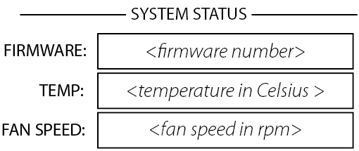
- Firmware – A three-section number identifying the major release, minor release, and maintenance release. For example, 5.0.06.
- Temp – The current chassis temperature of the Core.
- Compromised threshold = 60° C
- Fault threshold = 70° C
- Fan Speed – This number varies with the temperature.
LAN A
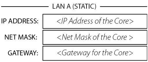
- Static or Auto – Displays next to LAN A, indicates if the Core's IP Address is Static or Automatic.
- IP Address – The IP Address assigned to the Core's LAN A. LAN A is the primary Q-LAN connection to the Core, and is required.
- Net Mask – The Net Mask assigned to the Core.
- Gateway – The Gateway assigned to the Core.
Note: You can edit this information in Core Manager.
LAN B
LAN B is used for redundancy, and is not required. The information is the same as LAN A.
Input / Flex In Channels Status
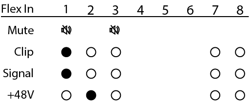
The Input and Flex Input screens show the Mute, Clip, Signal, and +48V (phantom power) for the eight Mic/Line input channels.
- Mute – Displays a "muted loudspeaker" when the channel is muted.
- Clip – Displays a solid circle under the channel having an input signal that is overdriving the associated channel input.
- Signal – Displays a solid circle when there is a signal present on the associated channel.
- +48V – Displays a solid circle when the phantom power is turned on for the associated channel.
Note: If the Flex channel is set to Output, there is no information for that channel on the Flex In screen.
Output / Flex Out Channels Status
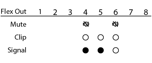
The Output and Flex Output screens show the Mute, Clip, and Signal, for the eight Mic/Line output channels.
- Mute – Displays a "muted loudspeaker" when the channel is muted.
- Clip – Displays a solid circle under the channel having an output signal over driving the associated channel output.
- Signal – Displays a solid circle when there is a signal present on the associated channel.
Note: If a Flex channel is set to Input, there is no information shown under the same channel on the Flex Out screen.
The POTS Controller component controls the features of the Q-SYS interface with a Plain Old Telephone Service (POTS).
If you are connecting to an analog phone system, you can connect from the wall RJ-11 jack directly to Q-SYS hardware supporting a POTS connection:
- The Core 110f and Core 110c provide a single RJ-11 telephone connection.
- The CTEL4 – Analog Telephony Card provides four RJ-11 telephone connections.
If you are connecting to a digital system, you can use an FXO Gateway that has an analog POTS connection and a network connection. For more information, visit the POTS Controller topic.
|
Technical Specifications |
|
|---|---|
| Input / Output Impedance |
600 ohms, nominal |
| Frequency Response |
300Hz - 3.3kHz +/- 0.5dB |
| Dynamic Range |
54 dB |
| Station Port Compatibility |
Two-wire ring start |
| Ringer Equivalence |
CTEL4: 0.0B Core 110f: 0.1 Core 11c: 0.1 |
| Electronic or 1A2 Line Key |
No1 |
| PABX Loop |
No1 |
| Trunk Port Compatibility |
Two-wire loop start |
| Number of phone lines |
CTEL4: 4 lines Core 110f: 1 line Core 110c: 1 line |
| Loop Current Interruption (CPC Pulse) |
Interpreted as line disconnect |
1. Each Q-SYS phone line is meant to be connected to a single PSTN line (FXO). It does not control a multi-line PBX or interface with an FXS.
