Mediacast Router
Use the Mediacast Router component to route multiple Mediacast streams to multiple destination Mediacast-capable devices. For example, you might want to see more than one camera on a single USB Video Bridge and switch between them. Or, you might want to create a design that handles video distribution for divisible or multipurpose room types.
Tip: The Mediacast Router configuration can easily be added to a Snapshot Bank for a simple and intuitive way to create presets.
Devices that send Mediacast streams
Devices that receive Mediacast streams
-
Any Q-SYS device with a USB Video Bridge. Refer to the USB Video Bridge topic to see a list of supported hardware.
 Input n
These pins receive incoming Mediacast streams from the Video Output pins of Mediacast-capable components.
Output n 
This pins send outgoing, routed Mediacast streams to the Video Input pins of Mediacast-capable components.
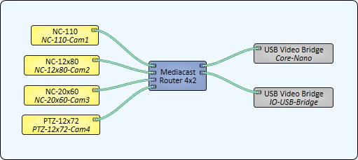
In this example, the Mediacast streams from four Q-SYS cameras can be routed to any of the USB Video Bridge-capable devices in the design – in this case, a Core Nano and an IO-USB Bridge.

Mediacast Router Properties
Input Count
Sets the number of input pins to receive Mediacast streams, from 1 to 255. The default is 2.
Output Count
Sets the number of output pins from which to send Mediacast streams, from 1 to 50. The default is 1.
Image Buttons
When set to Yes, the image that the camera is producing is displayed on the button. The default is No.
Graphic Properties
Label
Use the Label property to change the name of the component in the schematic. The Label property defaults to the component name. To learn more about renaming schematic elements, see Organizing Your Design.
Position
The coordinates reference a specific place in the schematic - for example,"100,100" (horizontal, vertical). 0,0 is the upper left corner of the schematic.
Fill
Sets the fill color of the component in the schematic.
Script Access Properties
Code Name
Displays the currently assign name for control access. You can use the auto-assigned name or customize it. Q-SYS will automatically check all Code Names in the design to ensure name is unique.
Script Access
Defines whether the component will be accessible by script and/or externally, or not at all. Choices include All, External, None (default), and Script.
Tip: Use Script Programmer Mode to quickly view the Script Access setting directly on the component in the design schematic without the need to disconnect from the Q-SYS Core processor.
Output n Select
The combo box indicates what Input is currently being routed for the selected Output. You can also specify the Input number to route to that Output.
Output n Input n Select
For each Output, click an Input's button to route it to that Output. Only one input can be active at a time for a given output.
|
Pin Name |
Value |
String |
Position |
Pins Available |
|---|---|---|---|---|
|
Output n |
||||
|
Input n Select |
0 1 |
false true |
0 1 |
Input / Output |
|
Select |
1 to 255 |
1 to 255 |
- |
Input / Output |
