Ping
Use this component to check whether a device is reachable on the network based on defined parameters.
Inputs and Outputs
Control components do not have traditional input and output pins. If a Control Pin is available for the component, an input or output will appear.
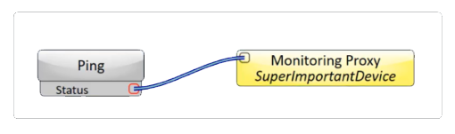
Control Pins represent the controls available in the component's Control Panel. Control Pins are used to link controls between Schematic Elements, and link to / from Control Scripts. Control Pin signal pins are represented by a  square, and the wiring is represented by a thick blue / white line.
In this example, we are using a Ping component with its Status control pin exposed wired to a Monitoring Proxy to ping the status.
Ping Properties
This component has no configurable properties.
Graphic Properties
Label
Use the Label property to change the name of the component in the schematic. The Label property defaults to the component name. To learn more about renaming schematic elements, see Organizing Your Design.
Position
The coordinates reference a specific place in the schematic - for example,"100,100" (horizontal, vertical). 0,0 is the upper left corner of the schematic.
Fill
Sets the fill color of the component in the schematic.
Script Access Properties
Code Name
Displays the currently assign name for control access. You can use the auto-assigned name or customize it. Q-SYS will automatically check all Code Names in the design to ensure name is unique.
Script Access
Defines whether the component will be accessible by script and/or externally, or not at all. Choices include All, External, None (default), and Script.
- None (default) - Not accessible by any script, plugin, or by Q-SYS Remote Control Protocol (QRC).
- Script - Can be accessed by scripts, such as Text Controller, Block Controllers, and plugins only.
- External - Can only be accessed by 3rd party controls systems using component commands from the Q-SYS Remote Control Protocol (QRC).
- All - No restrictions, can be accessed by 3rd party control systems via Q-SYS Remote Control Protocol (QRC), or script objects or plugin objects.
Tip: Use Script Programmer Mode to quickly view the Script Access setting directly on the component in the design schematic without the need to disconnect from the Q-SYS Core processor.
Ping Settings
Host Name
Specify the IP address of the destination device on the network for which you want to check network connectivity.
Packet Count
Specify the number of packets to send to the destination host, from 1 to 10 (default is 5).
Error Tolerance
Specify the number of packets that have to successfully reach the destination host to return an "OK" status, from 1 to 10 (default is 5). Set this value to be the same or lower than the Packet Count.
Ping Interval
Specify the amount of time to elapse before sending the next packet, from 1.00s to 10.0s (default is 1.00s).
Timeout
Specify the amount of time to wait for a host to indicate a packet was successfully received, from 2.00s to 10.0s (default is 2.00s). If a host reply is not received within the specified time, the request times out, and the sending of that packet is unsuccessful.
Start
Click this button to start the ping session.
Status
- While a ping session is in progress, the status shows as "Initializing".
- If the host can successfully be pinged, the status shows as "OK".
- If the host cannot be successfully pinged based on the defined Ping Settings, the status shows as "Fault - Time exceeded".
|
Pin Name |
Value |
String |
Position |
Pins Available |
|---|---|---|---|---|
|
Error Tolerance Count |
1 to 10 |
1 to 10 |
0.00 to 1.00 |
Input / Output |
|
Host Name |
(text) |
Input / Output |
||
|
Packet Count |
1 to 10 |
1 to 10 |
0.00 to 1.00 |
Input / Output |
|
Ping Interval |
1.00 to 10 |
1.00s to 10.0s |
0.00 to 1.00 |
Input / Output |
|
Start |
0 1 |
disabled enabled |
0 1 |
Input / Output |
|
Status |
(text) |
Output |
||
|
Timeout |
2.00 to 10 |
2.00s to 10.0s |
0.00 to 1.00 |
Input / Output |