Q-SYS VisionSuite Plugin (Seervision Control)
Use this plugin to control VisionSuite and other camera-centric automation.
Note: This plugin uses v2 encryption and must be used with 9.10.1 or above. Do not use this plugin with 9.10.0.
The Seervision Camera Control plugin is part of a larger experience known as VisionSuite. To properly commission VisionSuite, it is also recommended to set up the Automatic Camera Preset Recall (ACPR) plugin with the Seervision Integration property enabled.
VisionSuite integration is modular and can be used to satisfy many permutations of the following functionalities:
- Customizable presenter tracking shots and/or positions
- Customizable exclusion zones
- Vision-based zones
- Single or multi-presenter tracking
- Automatic camera switching
- Static camera views (dedicated whiteboard / document cameras etc)
- Audio-triggered camera preset recall and switching
- Per-camera, in-room face detection and auto framing
Legacy operation should only be commissioned with Seervision and ACPR plugins. Do not commission VisionSuite Designer systems alongside legacy plugins.
Note: VSA-100 does not support Seervision OS, but can use the legacy plugins running Q-SYS OS.
Before using this plugin, ensure your accelerator is properly provisioned and configured with the recommended VisionSuite version.
Note: SVS4 / SVS1 uses the .patch upgrade file type and VSA-100 uses the .squash file type. Ensure you have downloaded the correct upgrade file for your accelerator’s operating system.
Legacy with Seervision OS
Note: VisionSuite accelerators are provisioned with DHCP enabled by default. Discover your server's IP address using mDNS.
- Connect the accelerator to a network with a DHCP server.
- Open Q-SYS designer on a PC connected to your accelerator's network and add a new Seervision plugin to the schematic
- Navigate to the Q-SYS designer's menu bar File > Emulate. Open the Seervision plugin and click the Discover Servers button on the Setup page. Observe the list of server hostnames in any of the Discovered Servers dropdowns and select an accelerator to identify its IP address.
Note: Ensure the plugin’s VSA Model property is set to SVS1/4.
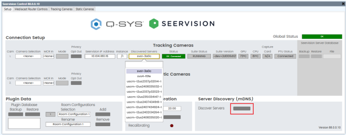
- Navigate to your accelerator's configuration webpage using its IP address in a web browser. A factory-fresh accelerator will look like this:
- Each SVS4-2U is capable of running 2 instances of AI processing simultaneously. Each SVS1-2U is capable of running 1 instance of AI processing. The instances are denoted by browser URLs:
- Instance 1: http://<IP_Address>/1
- Instance 2: http://<IP_Address>/2
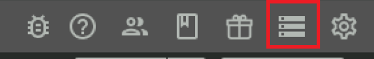
- You can easily navigate between instances on an SVS4-2U using these buttons at the top of the web page.
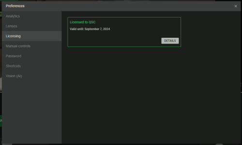
- Navigate to Settings > Licensing to verify your accelerator has a valid license. If needed, contact Q-SYS Support to renew.
Legacy with Q-SYS OS
You must have an accelerator status component added to your schematic to properly run a patch.
Note: Only VSA-100s ship with Q-SYS OS.
-
Connect the accelerator to a network with a DHCP server
-
Open Q-SYS designer on a PC connected to your accelerator's network and navigate to Configurator. Find your accelerator's entry and identify its IP address in the Peripheral Manager page.
Note: Ensure the plugin’s VSA Model property is set to VSA-100.
Note: Accelerator discovery via mDNS is no longer supported on Q-SYS OS and will not work in the plugin
-
Navigate to your accelerator's configuration webpage using its IP address in a web browser at port 8123:
http://<IP_Address>:8123
Note: The accelerator’s VisionSuite webpage uses http; however, the Peripheral Manager page uses https. Most web browsers will often attempt to automatically connect using https. Ensure you connect to the VisionSuite configuration page with http and not https.

-
Each VSA-100 is capable of running 2 instances of AI processing simultaneously. The instances are denoted by browser URLs:
- Instance 1: http://<IP_Address>:8123/1
- Instance 2: http://<IP_Address>:8123/2
-
You can easily navigate between instances on a VSA-100 using these buttons at the top of the web page.
Note: To enable the second instance on the VSA-100, please navigate to http://<IP_Address>:8123/2/operations/mangement, check "Launch when server starts", and click on the green Launch button.
-
For Q-SYS OS, licensing is no longer managed on the accelerator itself. Navigate to Core Manager > Licensing to verify your core has a valid license. If needed, contact Q-SYS Support to renew.
Note: Update your core to the latest version of Q-SYS Designer software before you install any VisionSuite licenses.
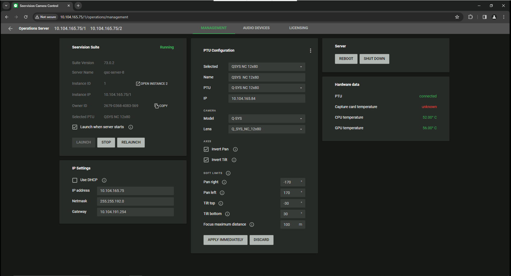
- Navigate to the Operations Server for your current instance using this button at the top of the web page:
- The Operations Server can be used to:
- View suite version, server name, and owner ID
- Stop or relaunch current the instance
- Configure network settings
- Configure PTU camera driver settings
- Monitor PTU connection status, GPU temperature, and CPU temperature.
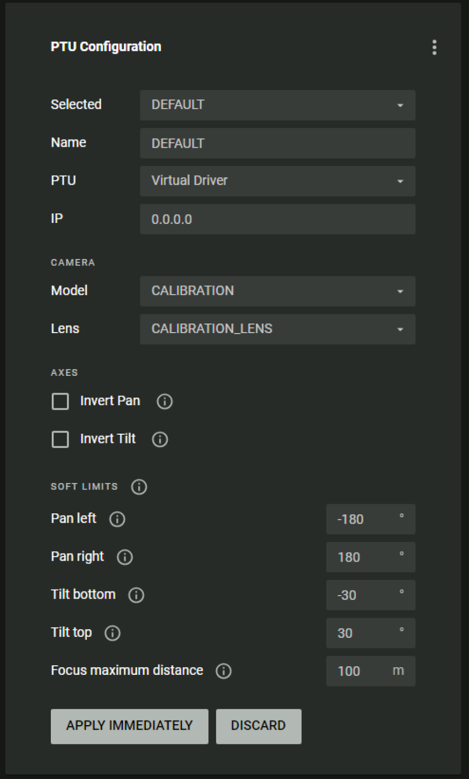
- A factory fresh server PTU Configuration will look like this:
- Enter a friendly name for a new configuration.
- Select the correct PTU model for your given camera from the PTU dropdown.
- For NC-12x80 select: Q-SYS NC 12x80 v9.10+
- For NC-20x60 select: Q-SYS NC 20x60 v9.10+
- For NC-110 select: Virtual Static Camera Driver
- Enter your Q-SYS camera's IP address in the IP text box.
- Select the calibration model from the Model dropdown menu: Q-SYS
- Select the lens for your given camera.
- For NC-12x80 select: Q-SYS_NC_12x80
- For NC-20x60 select: Q-SYS_NC_20x60
- For NC-110 select: Q-SYS_NC_12x80
- If the camera is installed upside down, check the Invert Pan and Invert Tilt boxes. If not, leave them unchecked.
- Click the Apply Immediately button. Once the PTU driver is loaded, the selected dropdown should reflect the latest configuration you just created.
- If applicable, repeat the above steps for instance 2 using a different camera.
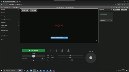
- Navigate to the main UI using the back button in the Operations Server.
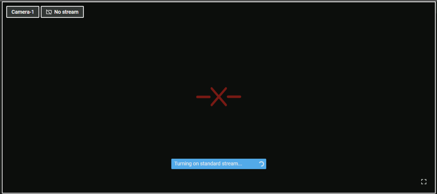
- If the RTSP stream is not configured for the instance, the preview will show black box with a red X like this:
- Configure your camera for multicast by setting its IP Streaming property to Multicast. Multicast camera streams are required for VisionSuite.
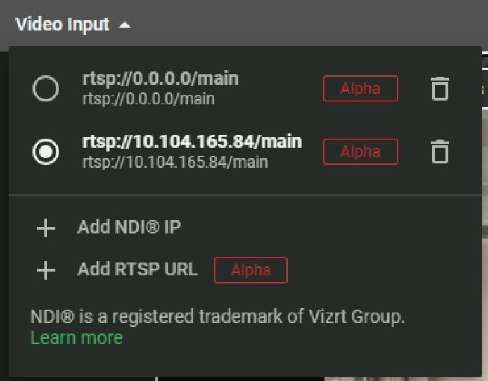
- Navigate to the Video Input dropdown menu and click "+ Add RTSP URL".
- Enter your camera's multicast IP stream and click the Add button
- For NC-90-G2, NC-110, NC-12x80, and NC-20x60
- rtsp://camera_ip_address>/main
- For NC-Pro15x
- rtsp://camera_ip/rtpstream/config1
- For NC-90-G2, NC-110, NC-12x80, and NC-20x60
- Select the radio selector for your new RTSP stream.
- In a few seconds, your RTSP preview should be functional.
- Navigate to the Streams section on the left sidebar for additional viewing options
- Video only: only shows incoming camera stream
- Computer vision: shows the skeletal model and bounding box overlaid on top of camera stream
- Focus peaking: shows lines overlaid on top of edges that are sharp and in focus.
- Zebra lines: shows diagonal lines overlaid on top of areas that are overexposed.

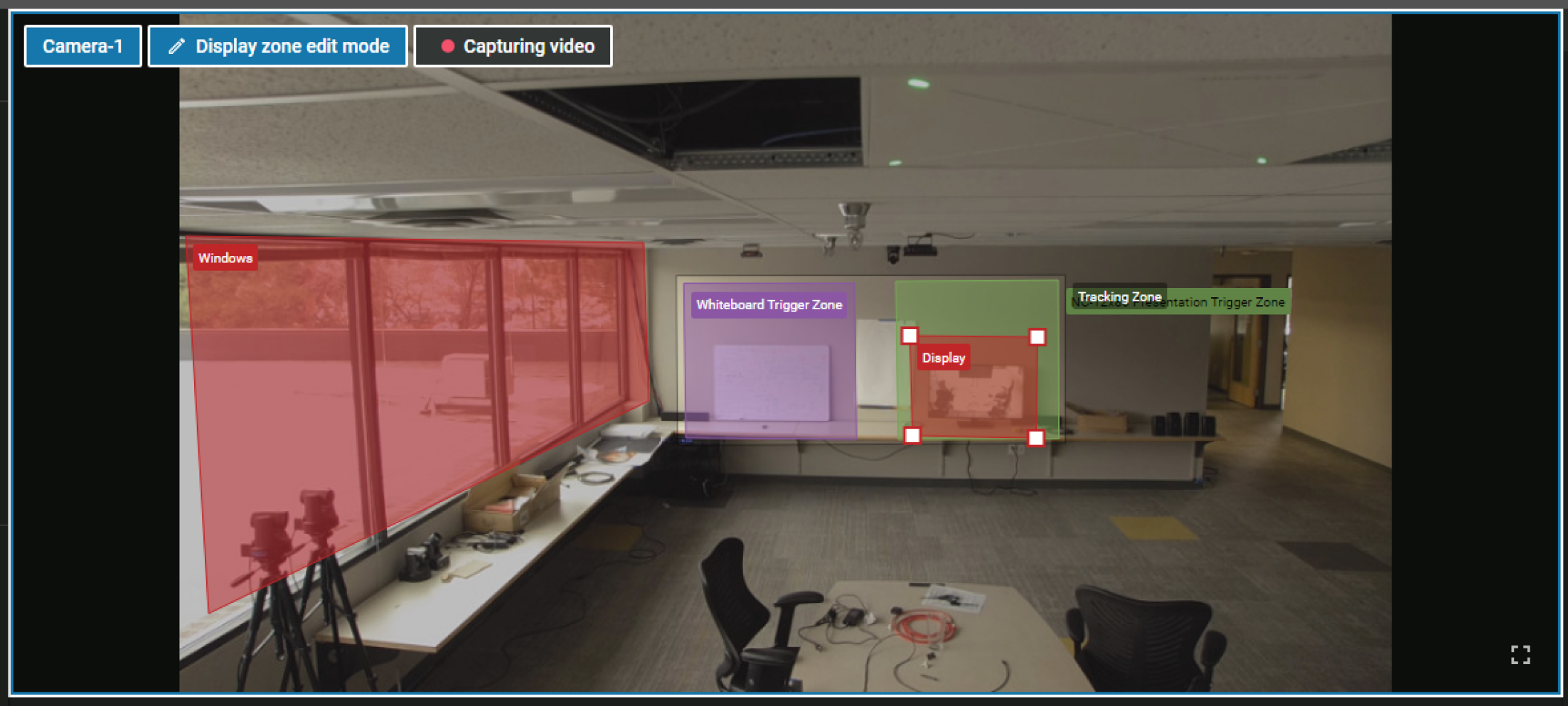
- Navigate to the Tracking Zones section and click "+" button.
- Hover over the newly created Tracking Zone and click the pencil button to edit the name and zone placement.
- Click the editable preview window to move the four corners of the polygon to your desired placement. Once you’ve modified the zone, click Save.
- Only configure one Tracking Zone per room configuration.
- Conductor Cameras should never use a Tracking Zone. Instead, Conductor Cameras should use one large Trigger Zone with a Leave Threshold of 3 seconds that overlaps with all other Trigger Zones. In the plugin, this Trigger Zone can be used to execute Fallback actions when Person Count = 0.
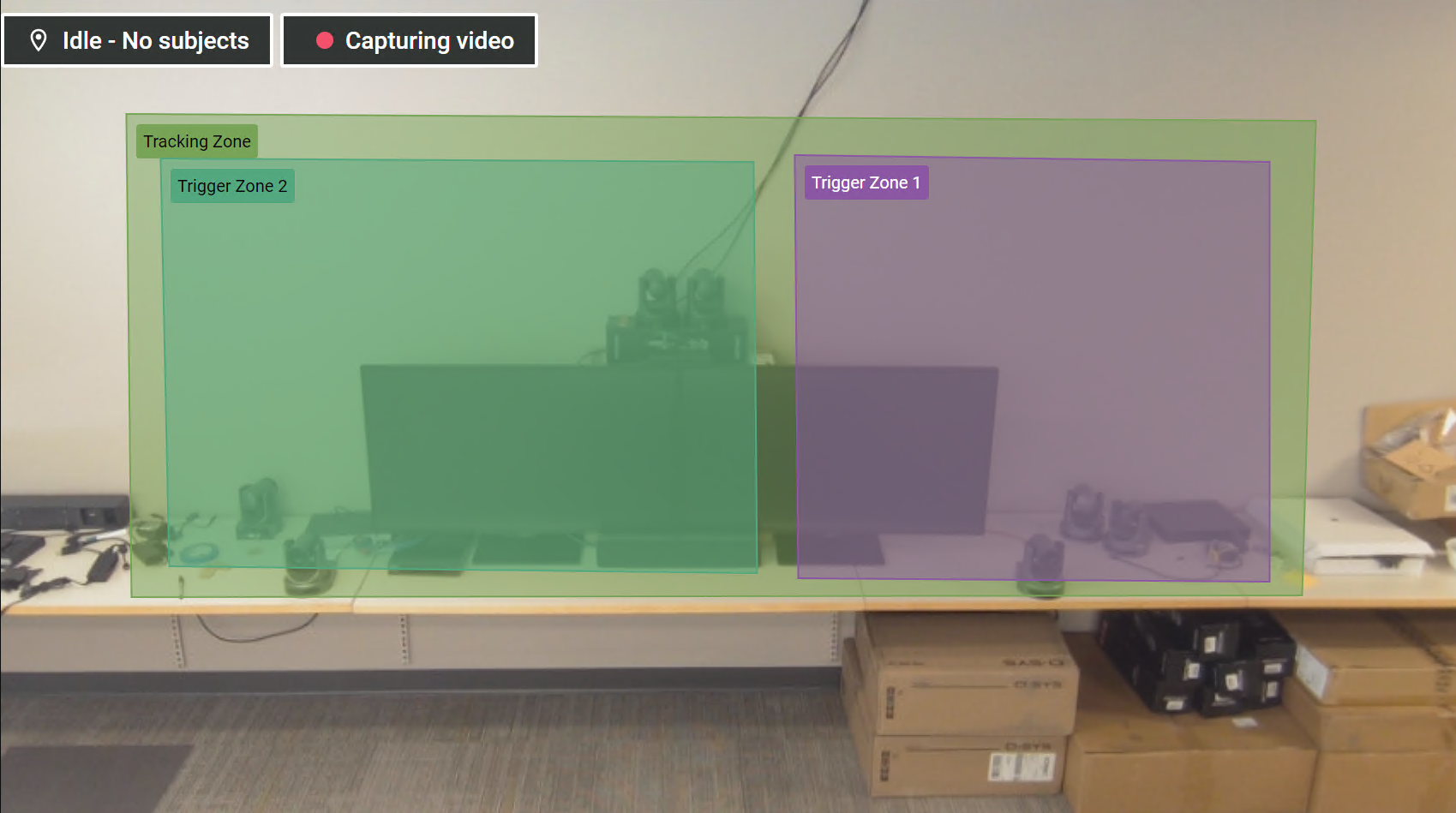
- For Tracking Zones, any subjects that enter the zone are considered trackable but they will not necessarily trigger a shot container to start presenter tracking. Any subjects that leave the Tracking Zone or subjects that enter the darker gray area are considered not trackable. This is most easily seen with the overlay provided by the computer vision Streams mode. Green overlay means trackable and Red overlay means not trackable.
- If a subject is being tracked and then leaves the Tracking Zone, the subject will be considered "lost" and a Fallback event will be generated.
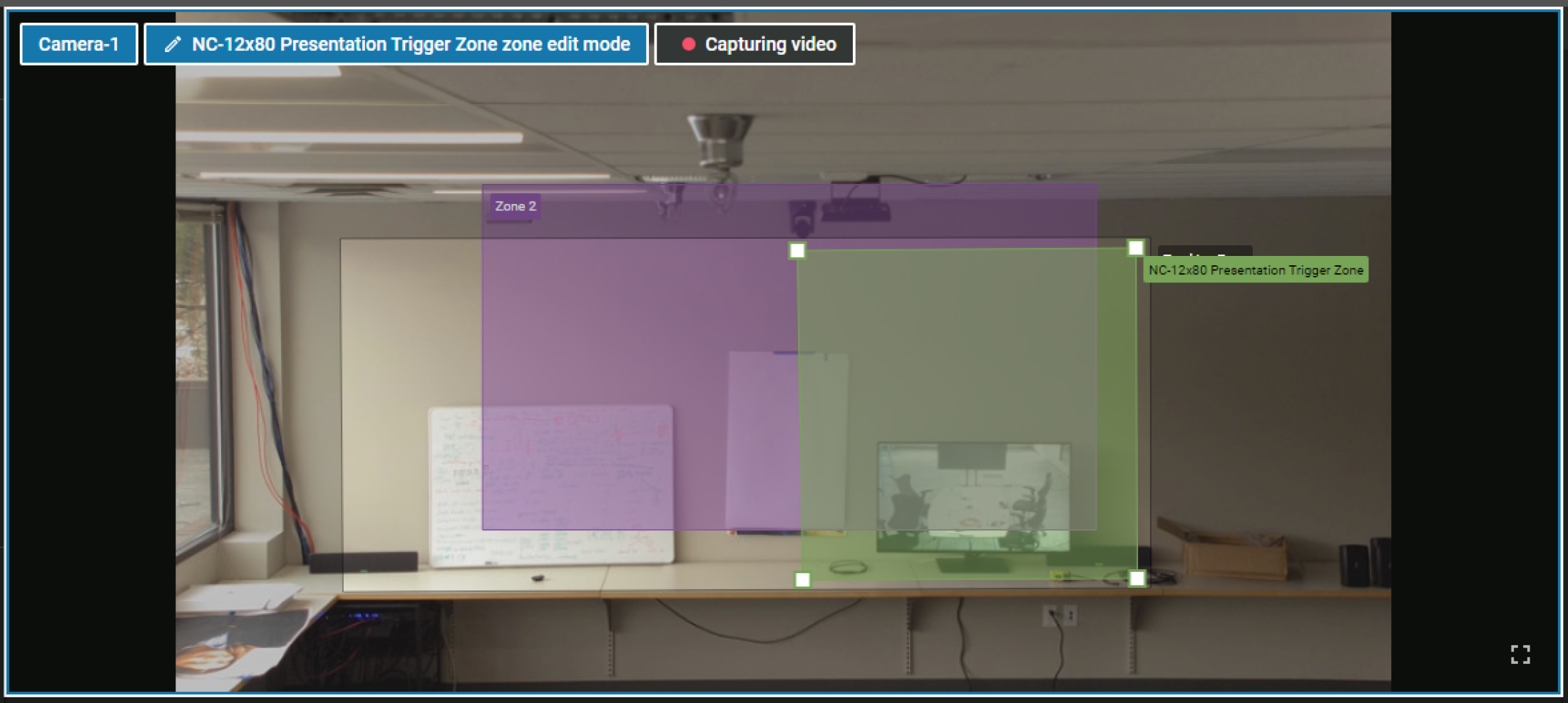
- Navigate to the Trigger Zones section and click the + button to Trigger Zones.
- Hover over a newly created Trigger Zone and click the pencil button to edit the name and zone placement.
- Click the editable preview window to move the four corners of the polygon to your desired placement. Once you’ve modified the zone, click Save.
- For Trigger Zones, any subjects that enter or leave the zone will generate enter and leave events to be consumed by the plugin. These zones do not necessarily trigger presenter tracking; they simply generate events.
- Create as many Trigger Zones as desired. The plugin can dynamically enable or disable applicable zones when changing room configurations.
- It can be useful to adjust enter and leave thresholds for Trigger Zones.
- Navigate to the Trigger Zone edit window.
- Scroll to the bottom of the edit window and configure thresholds as desired.
- Enter Threshold: Trigger Zones will wait for a subject to be in a zone for a specified amount of time before generating an Enter event.
- Leave Threshold: Trigger Zones will wait for a subject to be out of a zone for a specified amount of time before generating a Leave event.
Tip: Increasing the enter threshold can help avoid losing a tracked presenter when a non-presenter briefly walks through a zone. Increasing the leave threshold can help avoid resuming tracking on an invalid subject that has left the Tracking Zone.
- Navigate to the Exclusion Zones section and click + button.
- Hover over a newly created Trigger Zone and click the pencil button to edit the name and zone placement.
- Click the editable preview window to move the four corners of the polygon to your desired placement. Once you’ve modified the zone, click Save.
- For Exclusion Zones, any subjects that are 95% covered will be excluded from being trackable and/or generating Enter or Leave events. If an actively tracked presenter walks into an Exclusion Zone, even if they are 95% covered, they will not lose their tracking. Exclusion Zones are useful for in-room displays or signage that might show faces or glass conference room walls that might show people walking by in the hallway.
- Exclusion Zones are only useful for exclusion scenarios inside the Tracking Zone. Drawing Exclusion Zones outside of the Tracking Zone is not necessary.
- When the camera is tracking with a lot of zoom, sometimes zones can shift slightly. Draw Exclusion Zones slightly larger than needed to combat zone placement inaccuracy.
![]()
![]()
Notes:

Notes:

Notes:
- Create a Default / Fallback Position Container
Notes:
- Do not use the built-in reserved Fallback container. This automation is disabled by the plugin but the UI still shows it. Any Fallback behavior should only be configured with the plugin.
- Fallback events from the server are not relevant for Conductor Cameras because Conductor Cameras do not track. Instead, Leave events with Person Count = 0 are used.
- On a Tracking Camera, Fallback events are only generated by the server when a currently tracked subject walks out of the Tracking Zone or the subject is no longer present in the field of view for more than 3 seconds. Fallback events are not generated if tracking is not in progress.

- Move the camera's pan tilt and zoom controls to the desired default position.
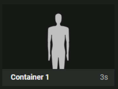
- Navigate to the main UI and click the "+ Position" button to create a new Position Container.
- Right click edit the name of the Position Container to conform to your naming convention.
Note: When recalled, Position Containers will move the camera to a known position with continuous movements using the VISCA protocol. This is not the same as an absolute coordinate recall in the Q-SYS camera component. Because of this recalling any position via a Position Container might not be 100% accurate.
- Create a presenter tracking Shot Container.
- Navigate to the main UI and click the arrow button next to the “+ Shot” button. There are a few standard options for framing:
- Full Body
- American
- Half Body
- Medium Close Up
- Right click edit the name of the Shot Container to conform to your naming convention.
- Create as many Shot Containers for your integration as needed.
Notes:
- When recalled, Shot Containers will attempt to track a presenter relative to the framing of the body graphic displayed in the container UI. For example: an American shot will have a looser crop than a Half Body shot.
American Shot - less cropping while tracking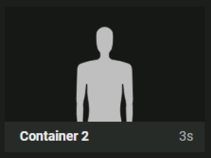
Half Body Shot - more cropping while tracking - It’s also possible to fine tune the position of the framing by using the editing window to drag the body graphic around or zoom in like this:
- When recalled, Shot Containers will attempt to track a presenter relative to the framing of the body graphic displayed in the container UI. For example: an American shot will have a looser crop than a Half Body shot.
- Navigate to the main UI and click the arrow button next to the “+ Shot” button. There are a few standard options for framing:
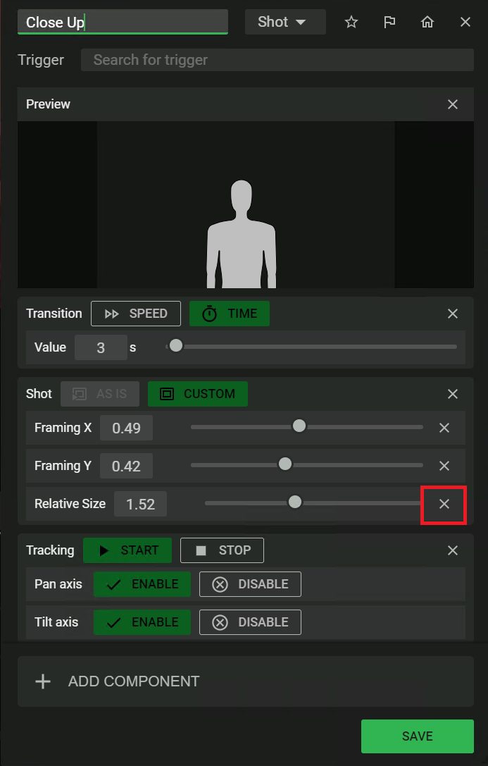
- NC-12x80 and NC-20x60 cameras can sometimes have undesirable focus behavior while zooming. It is possible to mitigate this by disabling adaptive zoom.
- Navigate to the Shot Container edit window and click the X button next to the Relative Size slider to remove it.
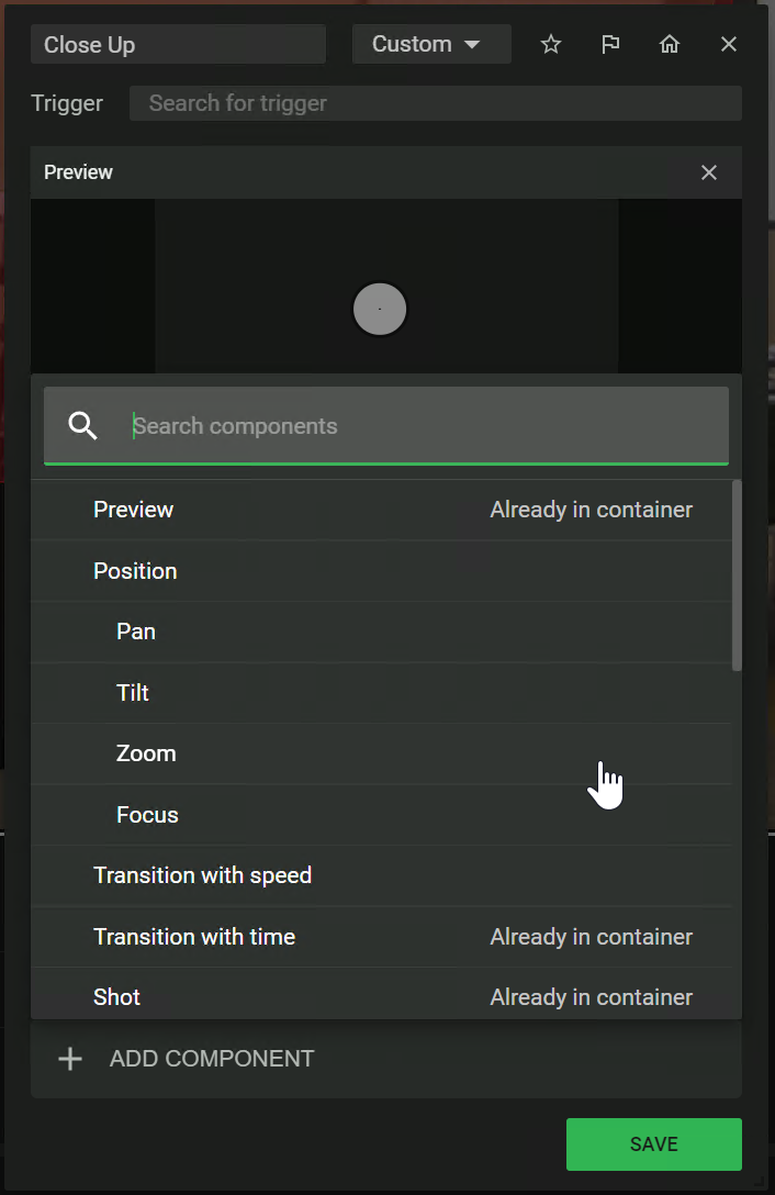
- Click on "ADD COMPONENT" at the bottom of the window and select Zoom from the pop-up menu.
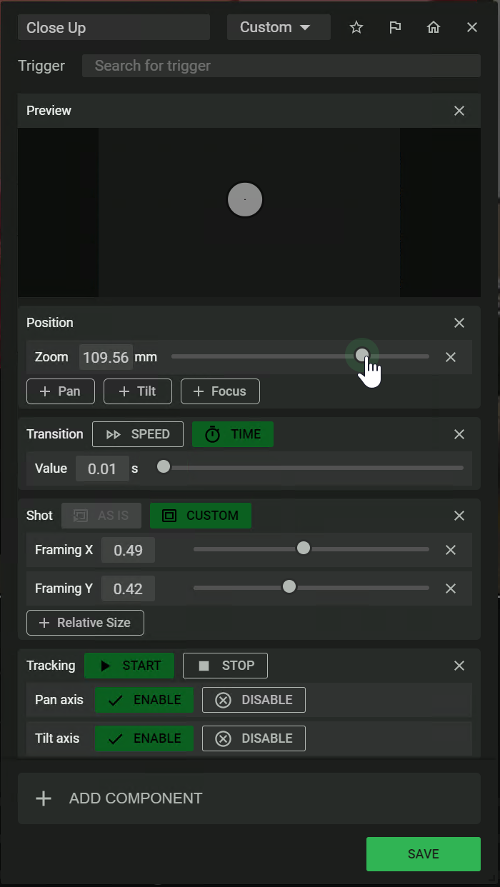
- Adjust the Zoom level as desired and click save.
- Now the Shot Container will only recall zoom to the specified level when it is initially recalled and it will not continuously adjust zoom as the presenter is tracked.
The primary functionality of this plugin is to connect to a Seervision instance, watch the events that are generated and then execute actions based on the conditions of those events. Subjects can move in or out of enabled Trigger Zones and the server will generate events to be consumed by the plugin.
Automation is programmed by configuring specific rows of controls listed under the Events and Actions headers.
There are two types of Seervision cameras that can be mapped to a Seervision instance to watch events:
- Tracking Cameras: These cameras are intended to mechanically pan, tilt, zoom, and focus to provide responsive presenter tracking while also maintaining perspective corrected Trigger Zone positions. NC-12x80 and NC-20x60 cameras are great choices for Tracking Cameras.
- Conductor Cameras: These cameras are not intended to pan, tilt, zoom, or focus and do not provide any presenter tracking. They only provide perspective corrected Trigger Zone positions. They should have the widest field of view as possible to maintain a bird's-eye view of the presentation space. They are primarily used to execute actions on other cameras. In many scenarios, this camera will only be used for vision-based triggers and its video will never be routed to an output. NC-110 cameras are a great choice for Conductor Cameras.
Note: For certain room division scenarios, you can program a Tracking Camera to function like a Conductor Camera, but you can never program a Conductor Camera to function like a Tracking Camera.
There is also a third type of Seervision camera that cannot be mapped to a Seervision instance:
- Static Cameras: These cameras are intended to be used for dedicated, static shots. It is possible to program several recallable position presets for a single camera; however, after the camera video has been routed to an output, it is not intended to move. These cameras do not provide any presenter tracking. Any Q-SYS camera models are a good choice for Static Cameras: NC-12x80, NC-20x60, or NC-110.
Note: Every VisionSuite integration must have at least one camera, a Mediacast Router component, and a Seervision plugin. Only one Mediacast Router is allowed per Seervision plugin.
- Drag one Seervision Camera Control plugin to the schematic.
- Modify properties to match your desired camera counts, zone counts and Reflect requirements.
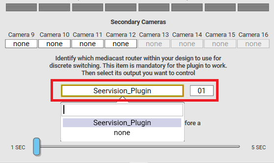
- Change the Seervision plugin's Code Name property to "Seervision_Plugin" and ensure Script Access = All.
- Drag one Mediacast Router component to the schematic.
- Change the Mediacast Router's Code Name property to "Mediacast_Router" and ensure Script Access = All.
- Add camera components to your inventory to satisfy your VisionSuite integration requirements. Ensure every camera has the IP Streaming property set to "Multicast Only".
- Specify a unique Code Name for each camera status component and ensure Script Access = All.
Note: Every Camera and Mediacast Router that is wired to a VisionSuite integration must have its component Script Access property set to All.
- Deploy or emulate your Q-SYS design.
- Navigate to the Setup tab in the Seervision plugin.
- For each camera in your VisionSuite integration, select the name that corresponds to your camera.
- For each Tracking and/or Conductor camera, enter the Seervision IP address and the corresponding instance number.
- The Seervision and ACPR plugins use the Camera Selection to provide privacy compatibility, IP streaming mode checks, and daily recalibration.
- Static Cameras can be uniquely selected per Room Configuration; however, Tracking and Conductor Cameras cannot.
Notes:
Note: Every Camera must have a configured MCR Input and MCR Output for every Room Configuration.
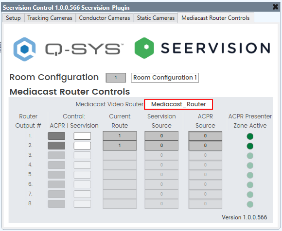
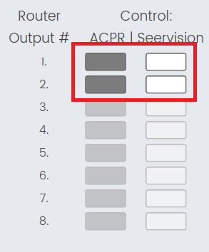
- Navigate to the Mediacast Router Controls tab and select your named Mediacast Router component from the Mediacast Video Router dropdown.
- Observe that the Mediacast Router controls on this page will automatically adapt to the number of outputs of your Mediacast Router. For example: If there are only 2 outputs configured, the plugin will only enable 2 rows of controls:
- If using ACPR and Seervision, add a new ACPR plugin to the schematic and ensure the ACPR plugin's Seervision Integration property is set to Yes. Enter "Seervision_Plugin" for the SV Plugin Code Name property.
- Deploy or emulate the design and select "Seervision_Plugin" from the ACPR plugin's Camera Router dropdown. If configuring multiple rooms, use a separate ACPR plugin for each Room Configuration and configure the Camera Router Output dropdown accordingly. For example: Room 1's ACPR plugin should use Camera Router Output 01 and Room 2's ACPR plugin should use Camera Router Output 02, etc.
- Now that the Mediacast Router is configured, navigate to the Setup tab and select the appropriate mapping for your wired cameras.
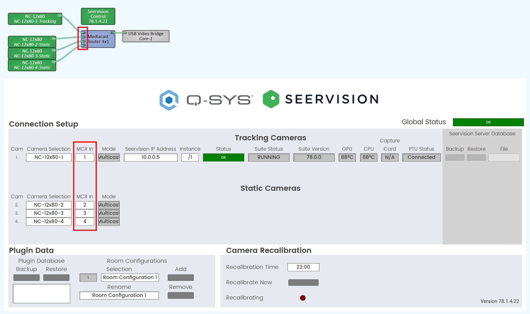
- If ACPR is not implemented, you can wire Seervision cameras to inputs 1 - 16. For example: you can map cameras 1 - 4 like this:
- If ACPR is implemented, it is highly recommended that you reserve the first 16 inputs for ACPR cameras. This means that Seervision camera inputs will start at 17. There must not be any input crossover between the ACPR plugin and the Seervision plugin. Seervision cameras must not be selected in the ACPR Setup tab. For example: you can map cameras 1 - 4 like this:
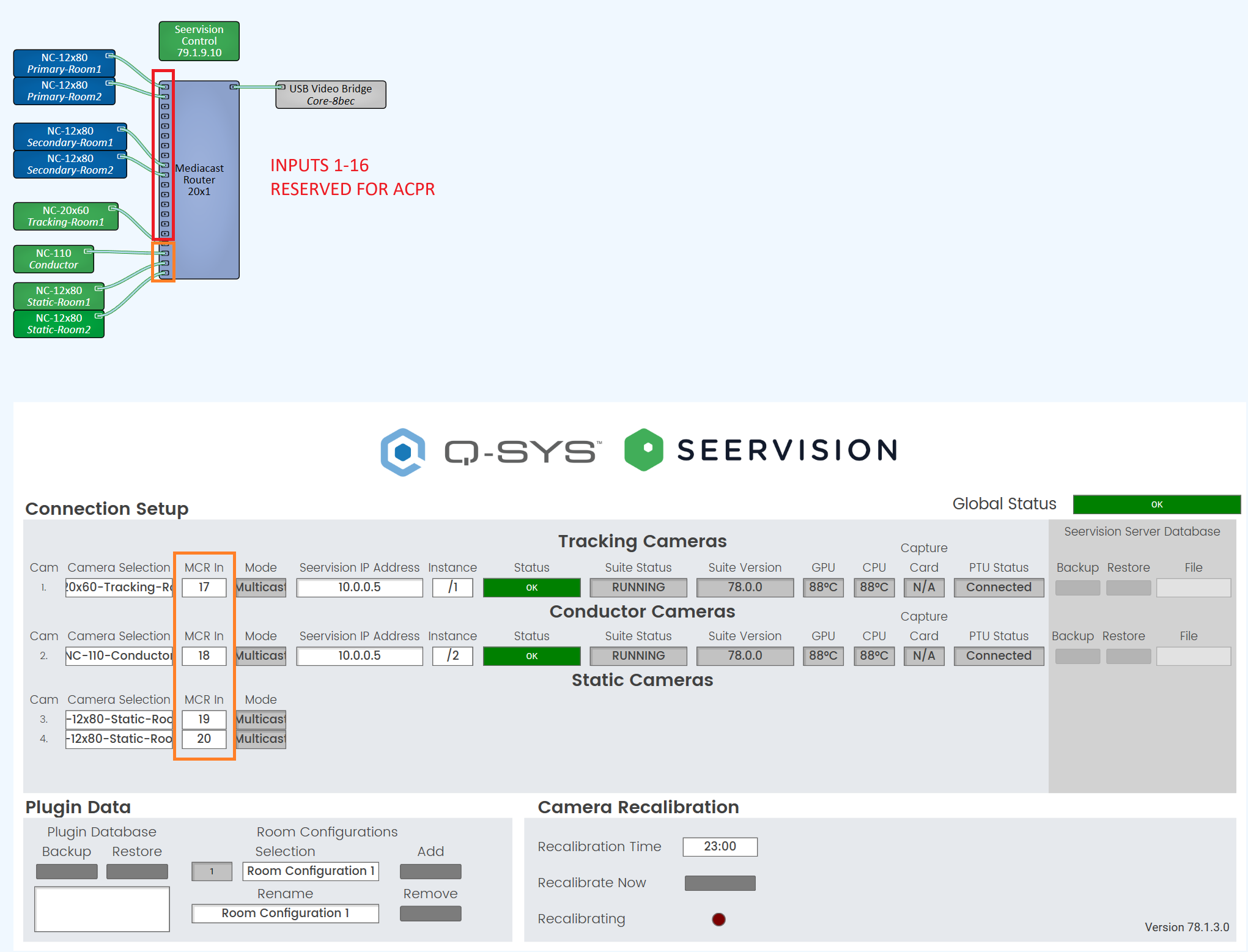
CAUTION: ACPR plugins should only access the Mediacast Router through a Seervision plugin. When an ACPR plugin is configured for "Seervision Integration", it will only list Seervision plugins for Camera Router selection.
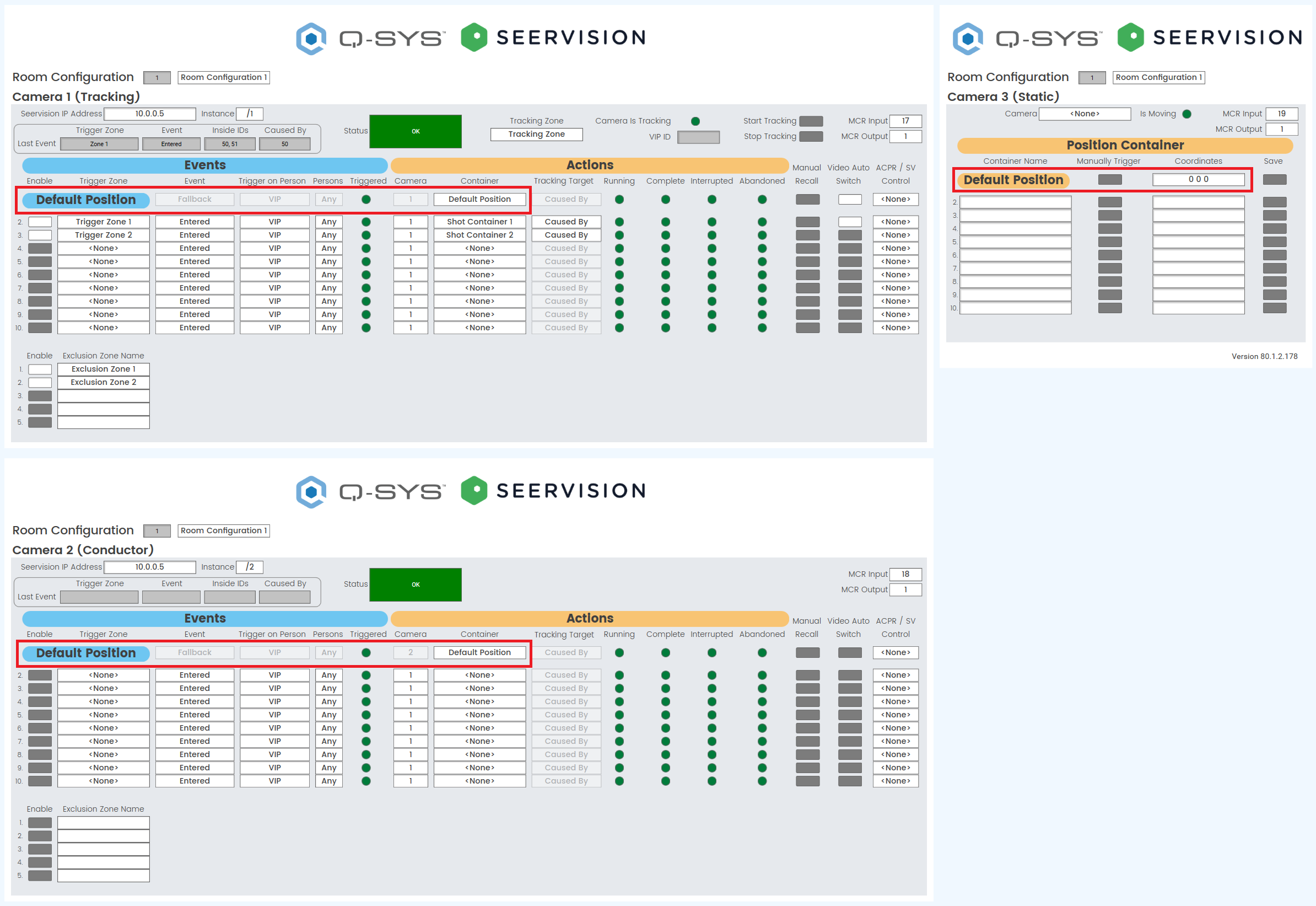
Note: Every Tracking, Conductor, and Static Camera must have a configured Default Position for every Room Configuration.
Note: The Default Position is used to return the camera to a known state when the system is either recalibrated, reconnected, or the Room Configuration changes. The Default Position for each camera is automatically recalled 60 seconds after recalibration has initiated. The Default Position is also automatically recalled anytime a Room Configuration change results in a different Mediacast Output selection for a particular camera. This is useful for room division scenarios because only cameras that change their Mediacast Outputs will be disrupted.
- Navigate to each applicable server instance and create a position container for the default position for each camera.
- Navigate to each Tracking and/or Conductor camera and select the position container for the Default Position row for each.
- Navigate to each Static Camera and enter coordinates for the Default Position row for each.
- Configure one of the Default Position rows with Auto Video Switch Enabled. This ensures the Mediacast Router is set to the desired starting input after recalibration and/or room configuration changes.
Tip: For Static Cameras, you can navigate to your desired position with the Q-SYS camera controls and click the Save button to save the current coordinates to the container.
Note: Every Room Configuration must have at least one Default Position configured with Video Auto Switch enabled per Mediacast Output. For example: If Room 1 uses Mediacast Output 1 and Room 2 uses Mediacast Output 2, both rooms must have at least one Default Position configured with Video Auto Switch enabled.
Note: The Seervision plugin assumes the use of at least one Mediacast Output per room. For advanced room division scenarios, the plugin uses Mediacast output-driven Fallback to properly recall Default Positions for cameras in rooms that need reconfiguration and avoid disrupting cameras in rooms that don't need reconfiguration. For example: In a 4 way divisible space, if Rooms 1,2,3,4 are all divided and the Room Configuration is changed such that Rooms 1,2,3 are combined, Cameras in Rooms 1,2,3 will receive Fallback events, but Room 4 will not.
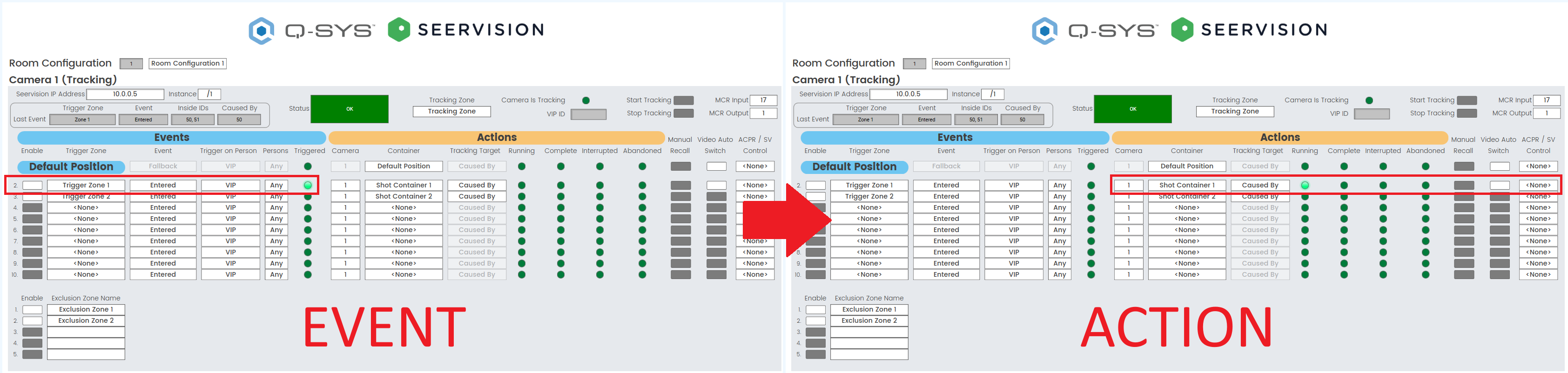
- Navigate to each Tracking and Conductor camera and configure the Events for each applicable row. When a defined Event matches all of the configured conditions, the Event will be triggered.
- Select the desired Trigger Zone from the Trigger Zone dropdown for each applicable row. When selected, the Enable button will automatically turn on.
- Select the desired Event type from the Event dropdown for each applicable row. The plugin can build automation using these event types:
- Entered: When a subject enters a zone the server will generate an Entered event.
- Leave: When a subject leaves a zone the server will generate a Leave event.
- Select the desired persons count from the Persons dropdown for each applicable row. The plugin can build automation using these Persons counts and will trigger when:
- Any: Any number of subjects are left in the zone.
- 0: No subjects are left in the zone. This selection only applies to Leave events.
- 1: One subject is left in the zone.
- 2+: Two or more subjects are left in the zone.
- Select the desired Trigger On Person option from the Trigger on Persons dropdown for each applicable row. The plugin can build advanced tracking state machines and will trigger when:
- Any Person: Any subject generates an event.
- VIP: Any subject generates an event while the camera is not actively tracking or a subject generates and event while the camera is actively tracking and their Caused By ID matches the VIP ID.
- Navigate to each Tracking and Conductor camera and configure the desired Actions for each applicable row.
- There are two types of Actions:
- Native: These actions are performed on the same camera that generated the received Event.
- Example 1: Tracking Camera starts presenter tracking.
- Example 2: Tracking Camera switches Mediacast Input.
- Non-native: These actions are performed on a different camera than the received Event.
- Example 1: Tracking Camera switches to Static Camera.
- Example 2: Conductor Camera starts presenter tracking on a Tracking Camera.
- Select the desired Camera number to which the configured Action will be applied.
- Based on the Camera number, select the Container that will be recalled.
- Select the desired Tracking Target option from the Tracking Target dropdown for each applicable row. The plugin can target Shot Containers on specific subjects:
- If the Action is Non-native tracking can target:
- Left: The subject that is most left in the field of view.
- Middle: The subject that is most center in the field of view.
- Right: The subject that is most right in the field of view.
- If the Action is Native tracking can target:
- Left: The subject that is most left in the field of view.
- Middle: The subject that is most center in the field of view.
- Right: The subject that is most right in the field of view.
- Caused By: The subject whose ID matches the Caused by ID.
- Inside: The subject whose ID is still left in the Trigger Zone.
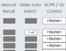
- If required, enable the Video Auto Switch button to switch to the specified camera after the container recall is complete.
- In later versions of the plugin, the a legend will be drawn on enabled Video Auto Switch button's that correctly have the associated input and output route number defined, to indicate what input #will be switched to what output # when the auto switch occurs. The dynamic legend is only shown when the target camera to switch to is different than the camera the row event was triggered on (in this case a user can just glance to the top right to see the IO pairing).
- In later versions of the plugin, the a legend will be drawn on enabled Video Auto Switch button's that correctly have the associated input and output route number defined, to indicate what input #will be switched to what output # when the auto switch occurs. The dynamic legend is only shown when the target camera to switch to is different than the camera the row event was triggered on (in this case a user can just glance to the top right to see the IO pairing).
- If required, select either ACPR or SV from the ACPR / SV Control dropdown to configure the ACPR | Seervision Control for the selected camera's MCR Output after the container recall is complete. This control functions like an override for a new mode. This control should normally be set to "None" unless a specific vision-based automation requires a change to the current setting.
Note: The Enable button can be used to turn zones on or off at the server. When a zone is turned off, no events will be generated when a subject enters or leaves that particular zone.
Note: Once the plugin is connected to the server, manipulating Trigger, Tracking, and/or Exclusion Zone states using the web interface is not recommended. Ideally, zones should only be enabled using the controls in the plugin. Any changes using the Trigger and/or Exclusion Zone buttons in the web interface will be reflected in the plugin's UI, but will not be written to the currently selected room configuration. Any changes to Tracking Zone buttons in the web interface, will not be reflected in the plugin's Tracking Zone dropdown.
Tip: Trigger On Person = VIP can be used to lock presenter tracking to a specific subject and prevent other subjects from stealing tracking.
Note: The Inside option is currently only useful for Leave events when Person Count is equal to 1. You cannot use this option to target multiple subjects in a zone.
Tip: You can set the ACPR / SV Control button states using vision-based Actions by using the ACPR / SV Control for any Conductor or Tracking camera event. This is useful if you want to configure a specific area for the presenter to walk into to turn on or off ACPR camera shots without using a UCI.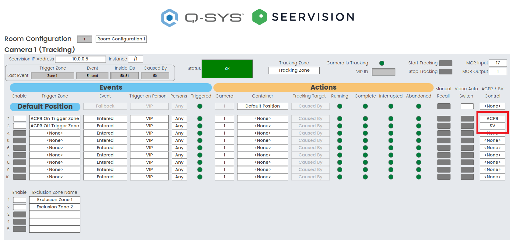
Tip: You can also use these controls in the Default Position row to restore a specific setting when a Room Configuration changes. This is useful when you want the ACPR / SV controls to be user configurable but want to restore the automation to a known default state the next time the Room Configuration is loaded.
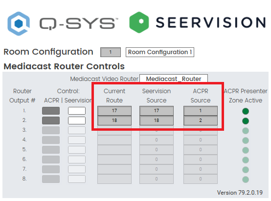
Note: The Seervision Camera Control plugin is the source of truth for Mediacast routing logic for every VisionSuite integration. ACPR and Seervision plugins are always writing their desired routes to the ACPR Source or Seervision Source controls for a given Mediacast Router output. The Seervision plugin ultimately decides which plugin can write to the Mediacast Router.
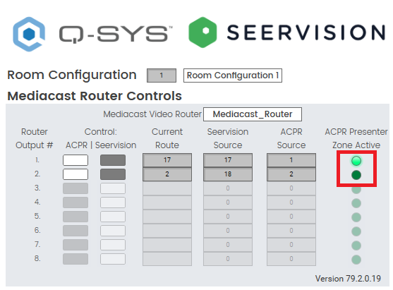
- Navigate to the Mediacast Router Controls tab and observe the controls.
- Each Mediacast Router output has three controls to indicate routing logic:
- Current Route: The Seervision plugin is constantly assessing the desired routes of both the Seervision plugin itself and ACPR. This control indicates current Mediacast Router input selection. This control will always match either the Seervision Source control or the ACPR Source control, but never both.
- Seervision Source: Any Trigger Zone vision-based logic can update this control. This control indicates the desired route of the Seervision plugin. This control does not necessarily indicate the current Mediacast Router input selection.
- ACPR Source: Any audio trigger-based logic from ACPR can update this control. This control indicates the desired route of the ACPR plugin. This control does not necessarily indicate the current Mediacast Router input selection.
- If using ACPR and Seervision configure at least one Seervision Zone in the ACPR plugin.
- Navigate to the ACPR plugin enable the green SV button in the desired Seervision Zone.
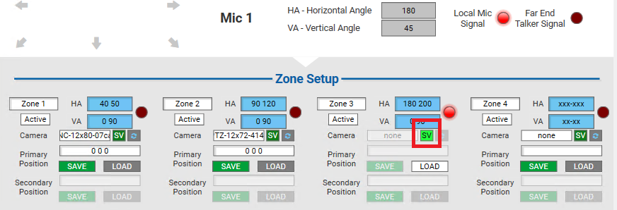
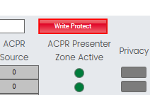
- When a Seervision zone is active longer than the specified ACPR PTZ Delay, the zone "preset" will be loaded. The Seervision plugin will write the current Seervision Source to the Current Route control and the Mediacast Router will switch to the desired Seervision camera. The Seervision plugin will also indicate when any Seervision zone is loaded by setting the ACPR Presenter Zone Active LED to true.
- When a Seervision zone is de-activated, the Seervision plugin will maintain the Current Route and the ACPR Presenter Zone Active LED will remain true until a new ACPR automation, that switches the Mediacast Router away from the Seervision camera, is executed.
Note: When a zone is configured as a Seervision zone any existing ACPR camera selection and/or preset will be ignored. Seervision zones can only be used to switch to a Seervision camera. They cannot be used to execute vision-based automation.
Tip: You can configure the ACPR home position as a Seervision zone. This is useful when you want the Mediacast Router to switch to the current Seervision camera when the home position timeout has expired.
- Configure the ACPR | Seervision controls for each Mediacast Router output.
- If using only Seervision, switch the ACPR | Seervision Control to Seervision for each desired output. This is the default selection for a fresh Seervision plugin.
- If using ACPR and Seervision:
- If you want to disable audio trigger-based camera switching and only use Trigger Zone vision-based camera switching, switch the ACPR | Seervision Control to Seervision for each desired output. This is useful when you want to prevent ACPR camera shots from interrupting the currently tracked presenter. For example: A professor can switch to Seervision on a UCI to lock out audience shots during an important part of their lecture and then switch back to ACPR to later allow audience shots for Q&A again.
- If you want to enable audio trigger-based camera switching and also use Trigger Zone vision-based camera switching, switch the ACPR | Seervision Control to ACPR.
- Later versions of the Seervision plugin include a "Write Protect" toggle button on the Mediacast Router page. Toggling this button on means that changes made to the ACPR | Seervision controls will not be saved in the current room configuration. When toggled off, changes made to those controls are immediately saved in the present room configuration. This setting will not affect the plugin's ability to recall control states for these controls when switching between room configurations
- The goal of this feature is to allow easy manipulation of routing setting when testing and commission, without worrying about modifying the existing settings.
Note: The Seervision Source should never be 0. Ensure you have Video Auto Switch configured for at least one of your Default Position rows to properly initialize the Seervision Source on plugin in startup.
Note: These controls allow you to cede the Seervision plugin's control to an ACPR plugin.
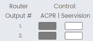
When the ACPR | Seervision Control is set to Seervision, the Seervision plugin will not cede control of the Mediacast router to ACPR. The Mediacast router will only switch to the Seervision Control plugin’s Seervision Source. The Mediacast router will not switch to any ACPR cameras.
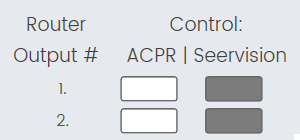
When the ACPR | Seervision Control is set to ACPR, the Seervision plugin cedes control of the Mediacast Router to ACPR. If audio events are detected in an ACPR Seervison Zone, the Mediacast Router will be switched to the Seervision plugin’s Seervision Source. If audio events are detected in a regular ACPR zone, the Mediacast Router will be switched to the Seervision Control plugin’s ACPR Route. The Mediacast router is able to switch to either ACPR cameras or Seervision cameras.
Note: For more information about ACPR, see the ACPR help file.
Note: The Seervision plugin has powerful native backup and restore functionality for its settings. This is further extended with a "snapshot" functionality called Room Configurations. Room Configurations allow the user to easily commission multiple configurations of zones, events, and actions with a simple dropdown. Room Configurations are a necessity for implementing room division. All of this data can be backed up and restored with a single json text string, eliminating Q-SYS design file dependency for VisionSuite applications.
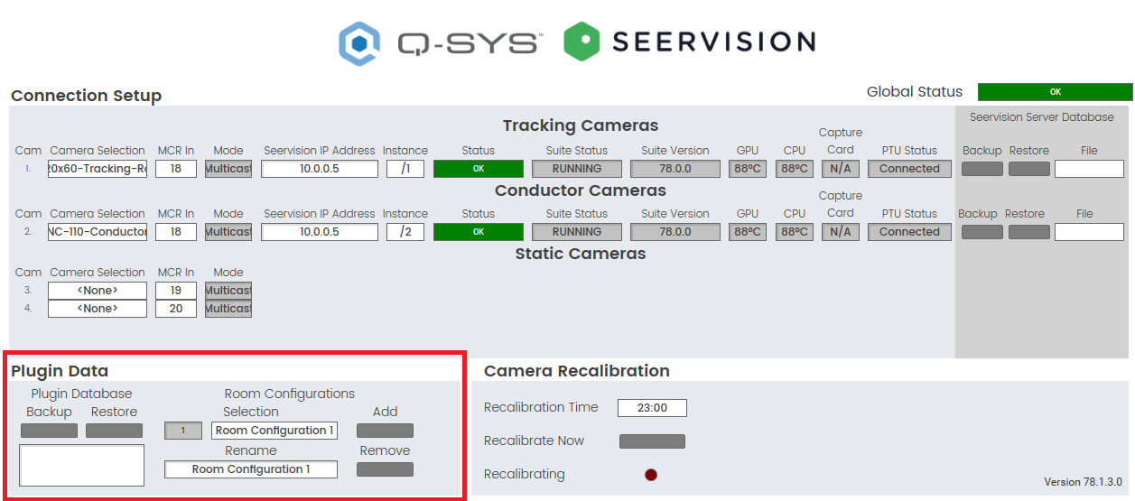
- Navigate to the Setup tab and observe the controls in the Plugin Data section:
- If required, add additional Room Configurations.
- Change any controls required to configure automation for a specific configuration. The selected Room Configuration is automatically saved anytime a control is changed.
- Room Configuration Selection: This dropdown control shows the currently selected Room Configuration. Changing the dropdown selection will automatically configure all plugin settings with the selected Room Configuration.
- Room Configuration Number: Each Room Configuration is assigned a selection index. This control shows the selection index of the currently loaded Room Configuration.
- Add: Click this button to add a new Room Configuration to the dropdown list. The new Room Configuration will copy all the settings of the previous Room Configuration to use as a starting point for the new configuration.
- Remove: Click this button to remove the currently selected Room Configuration. Each option above the removed configuration will shift its index down by one.
- Once all the Room Configurations are saved, back up the plugin data for future use and maintenance.
- Click the backup button to generate a plugin data backup json string. Copy this string out of the text box for future use.
- To restore, paste a valid string in the text box and click the restore button.
Tip: You can wire a Selector component to the Room Configuration Number input control pin to easily synchronize multiple plugins to a single Room Configuration Number. You can also match the Room Configuration Number against multiple conditions in lua scripts for more complex automation.
Note: Room Configurations apply to all controls except Seervision IP Addresses and Instances. These controls should not be dynamically configured.
Note: It is recommended to match your plugin properties to your plugin database. The plugin database does not have to match configured properties. If the restored database has more cameras or zones than the plugin’s properties, those cameras / zones will not be applied.
Note: Any existing configuration present in the text box will be overwritten and not appended.
Note: Separate from the plugin data backup, the Seervision plugin also has powerful backup and restore functionality for individual server instance settings. Server Database backups allow you to easily backup and restore all Zones, Containers, PTU settings and RTSP streams with a few clicks.
- Navigate to the Setup tab and click the backup button. A backup text file will be generated and stored in the Core Manager ~ Files ~ Seervision Server Configurations folder.
- To restore a backup, select a backup from the File dropdown and click the restore button.
Note: When cameras are in privacy mode they will not be recalibrated. For successful recalibration with auto privacy enabled, an external script must be used to take the cameras out of privacy. Contact Q-SYS support for the VisionSuite Privacy Recalibration script.
Note: VisionSuite has its own built-in logic that can automatically recall both Seervision and ACPR cameras to and from their Privacy positions based on USB activity. This logic is fully compatible with VisionSuite room division.
CAUTION: The native Auto-Privacy functionality in USB Video Bridge components is not compatible with room division and will interfere with VisionSuite integrations. Ensure that the native Auto Privacy buttons in all USB Video Bridge components are disabled. For example: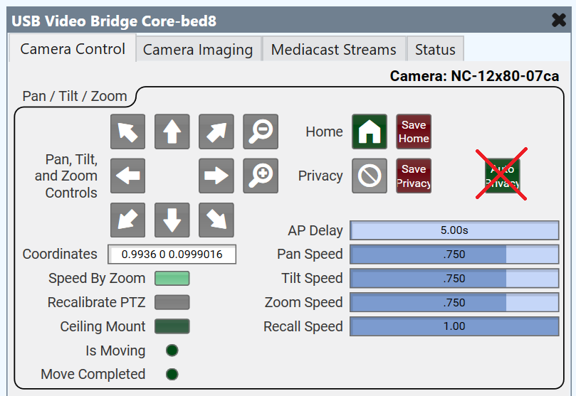
- Navigate to the Mediacast Router Controls tab and observe the USB Video Bridge (for Auto-Privacy) dropdowns for each Mediacast Output. By default, each dropdown is set to "Auto-Privacy Off" for each Mediacast Output.
- Specify a unique Code Name for each USB Video Bridge component and ensure Script Access = All.
- To enable Auto Privacy, navigate to the Mediacast Router Controls tab and select the desired USB Video Bridge from the USB Video Bridge (for Auto-Privacy) dropdown for the desired Mediacast Output.

- Once selected, the Seervision plugin will watch the USB activity in the selected USB Video Bridge component.
- When USB Video is active, all Seervision and ACPR cameras will recall their default positions.
- When USB Video is inactive and the AP Delay timer has expired, all Seervision and ACPR cameras will recall their Privacy positions.
- AP Delay can be adjusted to allow for more time before the cameras recall their Privacy positions.
- Enable or disable Privacy manually with the Privacy button for the desired Mediacast Output.
- In many cases, it can be useful to prevent certain cameras from entering Privacy. Navigate to the Setup tab and configure the Privacy Opt Out button for each camera as necessary.
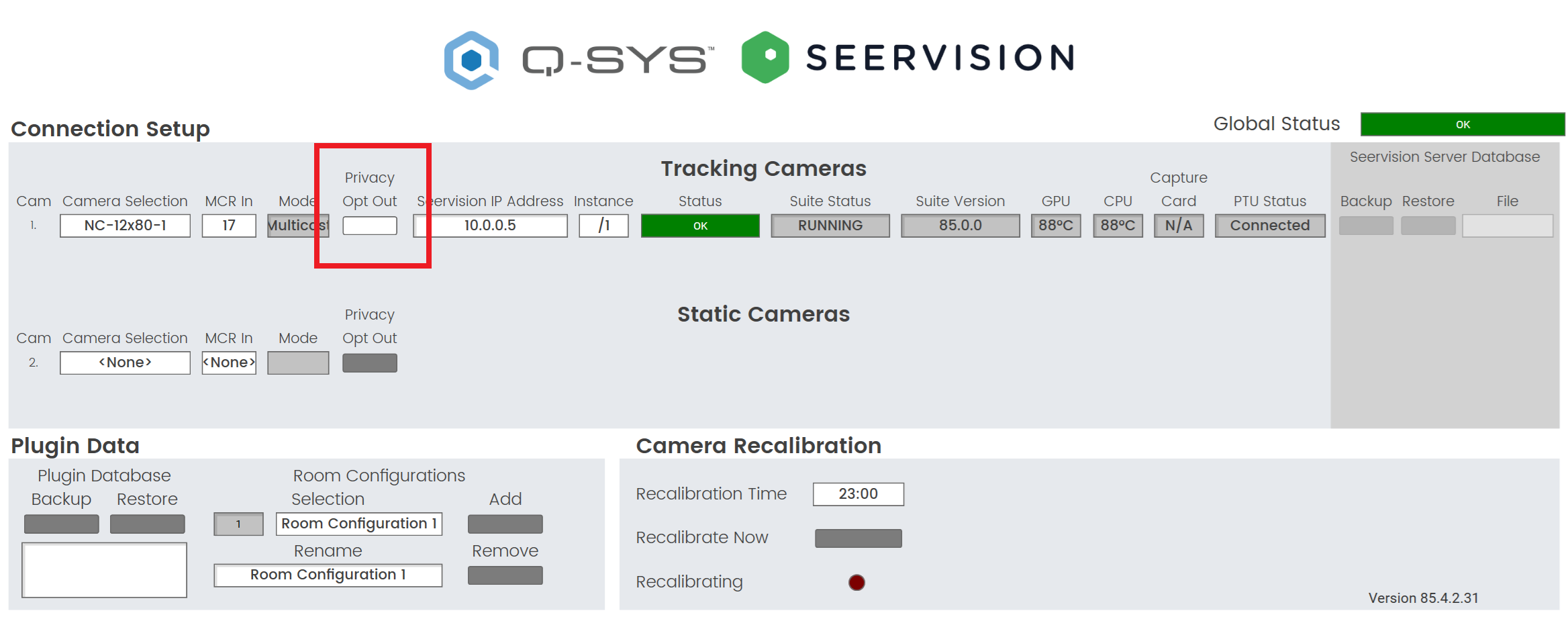
- When Privacy Opt Out is enabled, the camera will not participate in any Auto-Privacy logic.
- When Privacy Opt Out is disabled, the camera will participate in any Auto-Privacy logic.
Note: The IP streaming LEDs for Seervision Tracking and Conductor cameras will not turn off even when they are in their Privacy positions. The camera streams will remain active but will be injected with black video.
Note: This is a useful control to put on a UCI to allow a user to enter / exit Privacy while USB video is active.
Note: Privacy Opt Out is not available for any ACPR cameras.
Tip: For additional properties that are not listed, refer to the Properties Panel help topic for more information.
Is Managed
Select 'Yes' to add the plugin to your Inventory list, which makes the plugin's Status available for monitoring in Core Manager and Enterprise Manager. When enabled, you can then specify a Name and Location for the plugin, as with any other Inventory item.
VSA Model
Select “SVS1/4” when connecting to SVS1/4 running Seervision OS. Select “VSA-100” when connecting to a VSA-100 running Q-SYS OS.
For more information, refer to the Plugins topic in the Q-SYS Help.
Tracking Cams
Sets how many Tracking Cameras to use, from 1-8.
Static Cams
Sets how many Static Cameras to use, from 1-8.
Conductor Cams
Sets how many Conductor Cameras to use, from 1-8.
Trigger Zones
Sets how many Trigger Zones to use, from 1-25.
Exclusion Zones
Sets how many Trigger Zones to use, from 1-25.
Reconnect Interval(s)
Set the time interval(s) that must elapse after a connection is initialized for fallback to be triggered upon reconnection.
Lock
When set to 'Yes', all commissioning-time controls are disabled and users cannot change any settings without first unlocking the plugin after a design redeploy. Default setting is No.
Show Debug
Select 'Yes' to show the Debug Output window. For details, see the Debug Output topic in the Q-SYS Help.
Connection Setup
Global Status
Displays the main status of all Seervision servers and instances. If this status is in fault, the plugin is not properly configured.
Tracking Cameras / Static Cameras
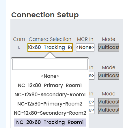
Camera Selection
Select the Code Name that corresponds to the wired camera status component. This control is used to provide privacy compatibility and daily recalibration.
MCR Input
Sets the Mediacast Input index for the specific Camera in a specific Room Configuration.
Mode
Each of the cameras can have different modes, such as privacy mode, streaming mode, or camera selection mode.
Privacy Opt Out
A toggle button for each Seervision camera. When this option is enabled, the camera will not be included in any privacy handling logic. Conversely, when it is disabled, the camera will participate in all privacy handling logic. By default, this option is set to disabled for new plugins.
Seervision Server IP Address
Sets the IP address that is used to connect to the server.
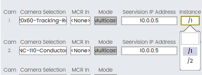
Instance
Sets the Instance that is used to connect to the server.
Discovered Servers
Contains server hostnames that were discovered using mDNS. Selecting one will add the associated IP address to the Server IP Address field.
Status
Displays the websocket connection status for a specific Instance.
Suite Status
Displays the Suite Status for a specific Instance.
Suite Version
Displays the Suite Version for a specific Instance.
GPU
Displays the GPU temperature in Celsius for a specific Instance.
CPU
Displays the CPU temperature in Celsius for a specific Instance.
Card
Displays the Capture Card temperature in Celsius for a specific Instance.
Note: There are currently no supported VisionSuite use cases that utilize capture cards.
Capture Card
Used to manage and monitor the temperature and status of the capture card within the system..
PTU Status
Displays the PTU connection status for a specific Instance.
Seervision Server Database
Backup
Click to generate a backup file of all the Seervision Instance settings: Containers, Trigger Zones, Thresholds, PTU Configuration, and RTSP settings. The backup file is stored in Core Manager > Files > Seervision Server Configurations. This file can be downloaded for future use using the in-built file management in Core Manager.
Restore
Click to restore a selected backup file.
File
Select a specific backup file from the dropdown menu. Dropdown menu options indicate any backup files stored in Core Manager > Files > Seervision Server Configurations.
Plugin Data
Database Backup
Click to generate a backup json string of all the plugin controls and configurations. Copy the string out of the Database text box to store for future use.
Database Restore
Click to restore a backup that has been entered into the Database text box.
Database (Text)
Enter or retrieve a Plugin Data json string.
Note: It is recommended to match your plugin properties to your plugin database. The plugin database does not have to match the configured properties. If the restored database has more cameras or zones than the plugin’s properties, those cameras / zones will not be applied.
Number
Sets and displays the index of the currently selected Room Configuration.
Room Configurations Selection
Sets the Room Configuration. All applicable controls and settings will be updated to the selected Room Configuration.
Rename
Click to rename the currently selected Room Configuration.
Add
Click to add Room Configurations.
Remove
Click to remove Room Configurations.
Clear
Used to reset or clear the current room configuration settings. This can be useful when you want to start fresh with a new configuration or remove any previously set configurations.
Event Log (text)
Displays the last item added to the event log. The information displayed includes the date/time, severity, category, and message.
Camera Recalibration
Recalibration Time
Sets the daily time for automatic recalibration of all Seervision and ACPR cameras.
Recalibrate Now
Click this to immediately recalibrate all Seervision and ACPR cameras.
Recalibrating LED
Indicates a pulse when recalibration has been activated.
Server Reboot
Allows users to mitigate issues with Seervision Servers becoming sluggish or unresponsive.
Reboot Day
Select the desired day for automatic server reboot, or choose "All" for daily reboots.
Reboot Time
Set the time for the server to automatically reboot.
Reboot Now
Press this button to immediately restart the server.
Server Discovery (mDNS)
Discover Servers
Uses mDNS to discover Seervision servers on the network, generates a list of discovered servers and their hostnames, and populates dropdowns on the setup page with this list.
Reconnection
Enable fallback on reconnect
Enables or disables the fallback mechanism upon reconnection for Seervision server cameras (tracking and conductor). When this option is enabled, the fallback will not be triggered when the server reconnects.
Debounce time (minutes)
Used to handle momentary websocket dropouts more gracefully. It includes a timer that determines how long a socket can be down before triggering the fallback mechanism. By setting a debounce time, the system can differentiate between brief, insignificant dropouts and more serious connection issues.
Room Configuration Number
Sets and displays the index of the currently selected Room Configuration.
Room Configurations Selection
Sets the Room Configuration. All applicable controls and settings will be updated to the selected Room Configuration.
Mediacast Router Controls
Mediacast Video Router
Sets the Mediacast Router that is used.
Write Protect
Prevents the Control ACPR | Seervision buttons from writing their state to the current Room Configuration.
Control ACPR | Seervision
Sets the control mode for each output.
Current Route
Displays the current route for a specific Mediacast Output.
Seervision Source
Displays the desired Seervision Source selection for a specific Mediacast Output.
ACPR Source
Displays the desired ACPR Source selection for a specific Mediacast Output.
ACPR Presenter Zone Active LED
Displays when a Seervision Zone is active in the ACPR plugin.
Privacy
Sets the Privacy state for the selected USB Video Bridge.
USB Video Bridge (for Auto-Privacy)
Sets the USB Video Bridge for Auto Privacy.
AP Delay
Sets the time in seconds the Auto-Privacy logic waits before invoking Privacy.
Room Configuration
Number
Sets and displays the index of the currently selected Room Configuration.
Room Configurations Selection
Sets the Room Configuration. All applicable controls and settings will be updated to the selected Room Configuration.
Tracking
Seervision IP Address
Displays the Seervision Server IP Address.
Instance
Option to choose the instance of /1 or /2 (if applicable).
Last Event Trigger Zone Name
Displays the Trigger Zone that was last triggered.
Last Event
Displays the type of Event that was last triggered.
Last Event Inside IDs
Displays the IDs of all subjects left in the Trigger Zone that was last triggered.
Last Event Caused By
Displays the ID of the subject that caused the last triggered Event.
Status
Component status is conveyed with the Status LED and Status box, which uses both color and text to indicate the current condition:
- OK (0): The device is functioning normally.
- Compromised (1): The device is functioning, but a non-fatal problem exists. Refer to the Status box for details.
- Fault (2): The device is malfunctioning or is not properly configured. Refer to the Status box for details.
- Not Present (3): If applicable to the device, this status appears when the device is not connected to the network and its Is Required component property is set to 'No'. This status also appears if the device component's Dynamically Paired property is set to 'Yes', pairing has not been assigned in Core Manager, and the device component's Is Required property is set to 'Yes'. See Dynamic Pairing.
- Unknown (3): This status appears during a Core reboot (for example, during a firmware update), or when a design is being uploaded to the Core and before it has started running.
- Missing (4): The device cannot be discovered.
- Initializing (5): The device is in the process of a firmware, patch, or configuration update, or the design is starting.
Tracking Zone
Sets the currently enabled Tracking Zone.
Note: VisionSuite only supports enabling one Tracking Zone at a time for each camera.
Camera Is Tracking LED
Indicates when a camera is tracking.
VIP ID
Indicates the ID of the currently tracked subject.
Start Tracking
Click this to immediately start tracking on a camera without using a Container recall.
Stop Tracking
Click this to immediately stop tracking on a camera without using a Container recall.
Start Tracking
Click this to immediately start tracking on a camera without using a Container recall.
MCR Input
Sets the Mediacast Input index for the specific Camera in a specific Room Configuration.
MCR Output
Sets the Mediacast Output index for the specific Camera in a specific Room Configuration.
Events
Enable
Click this to enable the Trigger Zone for the specific Event/Action row or to enable an Exclusion Zone.
Trigger Zone
Sets the Trigger Zone for the specific Event/Action row.
Event
Sets the Event type required to trigger the specific Event/Action row. Options: Enter, Leave, Fallback
Trigger On Person
Sets the subject specific filter based on tracking state required to trigger the specific Event/Action row. Options: VIP, Any Person.
- If not currently tracking:
- VIP: Any subject will trigger the Event.
- Any Person: Any subject will trigger the Event.
- If currently tracking:
- VIP: Only the currently tracked subject will trigger the Event.
- Any Person: Any subject will trigger the Event.
Persons
Sets the Persons count required to trigger the specific Event/Action row. Options: 0, 1, 2+, Any
Triggered LED
Indicates when an Event/Action row is triggered.
Exclusion Zone
Sets the Exclusion Zone.
Note: Unlike Tracking Zones, VisionSuite supports enabling multiple Exclusion Zones at a time for each camera.
Actions
Camera
Sets the camera index that the triggered action will affect.
Container
Sets the Container that is recalled. The dropdown menu options are dynamically generated based on the Camera index selection.
Tracking Target
Sets the subject specific filter based on tracking state required to trigger the specific Event/Action row. Options: VIP, Any Person.
- If Action is specified for the same camera as the Event received (Native Action), both location-based and ID-specific options can be used:
- Left: The subject that is most left if the field of view will be targeted.
- Middle: The subject that is most center if the field of view will be targeted.
- Right: The subject that is most right if the field of view will be targeted.
- Caused By: The subject whose ID matches the Last Event Caused By ID will be targeted.
- Inside: The subject whose ID is still left in the Trigger Zone will be targeted.
Note: The Inside option is currently only useful for Leave events when Person Count is equal to 1. You cannot use this option to target multiple subjects in a zone.
- If Action is specified for different camera than the Event received (Non-Native Action), only location-based options can be used:
- Left: The subject that is most left if the field of view will be targeted.
- Middle: The subject that is most center if the field of view will be targeted.
- Right: The subject that is most right if the field of view will be targeted.
Running LED
Indicates when a Container is being recalled. This LED will darken when the Container recall is completed.
Complete LED
Indicates when a Container recall is finished. When this LED is illuminated and Video Auto Switch is enabled for the Event/Action row, the Seervision Source will be updated. This LED will quickly darken after it has been activated.
Interrupted LED
Indicates when an Action is interrupted.
Abandoned LED
Indicates when an Action is abandoned.
Manual Recall
Click to manually execute the Action for the specified Event/Action row.
Video Auto Switch
Click to enable automatic Seervision Source update when Container recall is complete. The Seervision Source will be updated to the MCR Input specified for the selected Camera in the Event/Action row.
Tip:
If you want to update the Seervision Source before the container is complete, create an Event/Action row above the Container recall with the Container set to None.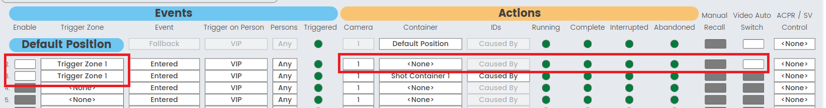
ACPR / SV Control
Sets the ACPR | Seervision Control triggered from an event. If an Action is triggered and ACPR is specified, the ACPR | Seervision Control for the specified MCR Output will change to ACPR mode. If an Action is triggered and SV is specified, the ACPR | Seervision Control for the specified MCR Output will change to SV mode.
Room Configuration Number
Sets and displays the index of the currently selected Room Configuration.
Room Configurations Selection
Sets the Room Configuration. All applicable controls and settings will be updated to the selected Room Configuration.
Camera (Static)
Sets the camera index that the triggered action will affect.
Is Moving LED
LED is lit when the camera is moving.
MCR Input
Sets the Mediacast Input index for the specific Camera in a specific Room Configuration.
MCR Output
Sets the Mediacast Output index for the specific Camera in a specific Room Configuration.
Position Container
Container Name
Names the Position Container that is saved.
Manually Trigger
Click to manually recall a Position Container.
Coordinates
Displays and modifies the current coordinates of the specific Static Camera.
Save
Saves the Name and current coordinates of the specific Static Camera to the specified Position Container.
|
Pin Name |
Value |
String |
Position |
Pins Available |
|---|---|---|---|---|
|
Conductor Cameras / Camera n |
||||
|
Exclusion Zone n |
||||
|
Enable |
0 1 |
false true |
0 1 |
Input / Output |
|
Name |
(string) |
Input / Output |
||
|
Trigger Zone n |
||||
|
ACPR Enable/Disable |
(string) |
Input / Output |
||
|
Camera Number |
(string) |
Input / Output |
||
|
Container Abandoned |
0 1 |
false true |
0 1 |
Output |
|
Container Action ID |
(string) |
Input / Output |
||
|
Container Complete |
0 1 |
false true |
0 1 |
Output |
|
Container Interrupted |
0 1 |
false true |
0 1 |
Output |
|
Container Name |
(string) |
Input / Output |
||
|
Container Running |
0 1 |
false true |
0 1 |
Output |
|
Enable |
0 1 |
false true |
0 1 |
Input / Output |
|
Event Type |
(string) |
Input / Output |
||
|
Manual Recall |
(trigger) |
Input / Output |
||
|
Name |
(string) |
Input / Output |
||
|
Number Of People |
(string) |
Input / Output |
||
|
Trigger On Person |
(string) |
Input / Output |
||
|
Video Auto Switch |
0 1 |
false true |
0 1 |
Input / Output |
|
Zone Name |
(string) |
Input / Output |
||
|
Last Event Caused By |
(string) |
Input / Output |
||
|
Last Event Type |
(string) |
Input / Output |
||
|
Last Event Inside IDs |
(string) |
Input / Output |
||
|
Last Event Zone Name |
(string) |
Input / Output |
||
|
Mediacast Router Input |
(string) |
Input / Output |
||
|
Mediacast Router Output |
(string) |
Input / Output |
||
|
Mediacast Router Controls |
||||
|
Output n |
||||
|
ACPR Output Select Control |
0 1 |
false true |
0 1 |
Input / Output |
|
ACPR Presenter Zone Active |
0 1 |
false true |
0 1 |
Output |
|
ACPR Output Source |
(string) |
Output |
||
|
Auto Privacy Delay |
5 600 |
5 600 |
5 600 |
Input / Output |
|
Current Route |
(string) |
Output |
||
|
Privacy Toggle |
0 1 |
false true |
0 1 |
Input / Output |
|
Seervision Output Select Control |
(string) |
Output |
||
|
Seervision Source |
(string) |
Output |
||
|
Video Bridge Selection |
(string) |
Input / Output |
||
|
Mediacast Video Router Select |
(string) |
Input / Output |
||
|
Write Protect |
0 1 |
false true |
0 1 |
Input / Output |
|
Setup |
||||
|
Conductor Cameras / Camera n |
||||
|
Capture Card Temperature |
(string) |
Output |
||
|
Connection Status |
(string) |
Output |
||
|
CPU Temperature |
(string) |
Output |
||
|
GPU Temperature |
(string) |
Output |
||
|
PTU Status |
(string) |
Output |
||
|
Camera Selection |
(string) |
Input / Output |
||
|
Camera Streaming Mode |
(string) |
Input / Output |
||
|
Privacy Opt Out |
0 1 |
false true |
0 1 |
Output |
|
Seervision IP Address |
(string) |
Input / Output |
||
|
Discovered Servers |
(string) |
Output |
||
|
Server Backup |
(trigger) |
Input / Output |
||
|
Server Configuration File |
(string) |
Input / Output |
||
|
Server Instance |
(string) |
Input / Output |
||
|
Server Restore |
(trigger) |
Input / Output |
||
|
Suite Status |
(string) |
Output |
||
|
Suite Version |
(string) |
Output |
||
|
Static Cameras / Camera n |
||||
|
Camera Selection |
(string) |
Input / Output |
||
|
Camera Streaming Mode |
(string) |
Input / Output |
||
|
Privacy Opt Out |
0 1 |
false true |
0 1 |
Output |
|
Tracking Cameras / Camera n |
||||
|
Capture Card Temperature |
(string) |
Output |
||
|
Connection Status |
(string) |
Output |
||
|
CPU Temperature |
(string) |
Output |
||
|
GPU Temperature |
(string) |
Output |
||
|
PTU Status |
(string) |
Output |
||
|
Camera Selection |
(string) |
Input / Output |
||
|
Seervision Camera Streaming Mode |
(string) |
Input / Output |
||
|
Privacy Opt Out |
0 1 |
false true |
0 1 |
Output |
|
Seervision IP Address |
(string) |
Input / Output |
||
|
Discovered Servers |
(string) |
Output |
||
|
Server Backup |
(trigger) |
Input / Output |
||
|
Server Configuration File |
(string) |
Input / Output |
||
|
Server Instance |
(string) |
Input / Output |
||
|
Server Restore |
(trigger) |
Input / Output |
||
|
Suite Status |
(string) |
Output |
||
|
Suite Version |
(string) |
Output |
||
|
Global Status |
(string) |
Output |
||
|
Plugin Database Backup |
(trigger) |
Input / Output |
||
|
Plugin Database Restore |
(trigger) |
Input / Output |
||
|
Plugin Database Text |
(string) |
Input / Output |
||
|
Recalibrate Now |
(trigger) |
Input / Output |
||
|
Recalibrating |
0 1 |
false true |
0 1 |
Output |
|
Recalibration Time |
(string) |
Input / Output |
||
|
Discover Servers |
(trigger) |
Input / Output |
||
|
Rename Room Configuration |
(string) |
Input / Output |
||
|
Room Configuration Add |
(trigger) |
Input / Output |
||
|
Rename Room Name |
(string) |
Input / Output |
||
|
Room Configuration Number |
(string) |
Output |
||
|
Room Configuration Remove |
(trigger) |
Input / Output |
||
|
Static Cameras / Camera n |
||||
|
Zone n |
||||
|
Container Name |
(string) |
Output |
||
|
Coordinates |
- |
Pan = -0.9936 to +0.9936 Tilt = -0.9936 to 2.9808 Zoom = 0.000000 to 1 (Coordinates are separated by a space.) |
- |
Input / Output |
|
Manually Trigger |
(trigger) |
Input / Output |
||
|
Save Coordinates |
(trigger) |
Input / Output |
||
|
Tracking Cameras / Camera n |
||||
|
Exclusion Zone n |
||||
|
Enable |
0 1 |
false true |
0 1 |
Input / Output |
|
Name |
(string) |
Input / Output |
||
|
Trigger Zone n |
||||
|
ACPR Enable/Disable |
(string) |
Input / Output |
||
|
Camera Number |
(string) |
Input / Output |
||
|
Container Abandoned |
0 1 |
false true |
0 1 |
Output |
|
Container Action ID |
(string) |
Input / Output |
||
|
Container Complete |
0 1 |
false true |
0 1 |
Output |
|
Container Interrupted |
0 1 |
false true |
0 1 |
Output |
|
Container Name |
(string) |
Input / Output |
||
|
Container Running |
0 1 |
false true |
0 1 |
Output |
|
Enable |
0 1 |
false true |
0 1 |
Input / Output |
|
Event Type |
(string) |
Input / Output |
||
|
Manual Recall |
(trigger) |
Input / Output |
||
|
Name |
(string) |
Input / Output |
||
|
Number Of People |
(string) |
Input / Output |
||
|
Trigger On Person |
(string) |
Input / Output |
||
|
Video Auto Switch |
0 1 |
false true |
0 1 |
Input / Output |
|
Zone Name |
(string) |
Input / Output |
||
|
Last Event Caused By |
(string) |
Input / Output |
||
|
Last Event Type |
(string) |
Input / Output |
||
|
Last Event Inside IDs |
(string) |
Input / Output |
||
|
Last Event Zone Name |
(string) |
Input / Output |
||
|
Mediacast Router Input |
(string) |
Input / Output |
||
|
Mediacast Router Output |
(string) |
Input / Output |
||
|
Is Tracking |
0 1 |
false true |
0 1 |
Output |
|
Mediacast Router Input |
(string) |
Input / Output |
||
|
Mediacast Router Output |
(string) |
Input / Output |
||
|
Start Tracking |
(trigger) |
Input / Output |
||
|
Stop Tracking |
(trigger) |
Input / Output |
||
|
VIP ID |
(string) |
Input / Output |
||
|
Tracking Zone |
(string) |
Input / Output |
||
|
Disable1 |
0 1 |
disabled enabled |
0 1 |
Input / Output |