Status (NV-32-H)
The NV-32-H Status component provides detailed information about the NV-32-H, including hardware health, network AV source details and statistics, Q-SYS Core audio streaming details (if applicable), and USB audio and video bridging details (if enabled).
 Properties
Tip: For additional properties that are not listed, refer to the Properties Panel help topic for more information.
HDMI / Shift AV
Device Type
Can set the NV-32-H as Shift Encoder, Decoder, or Mediacast Encoder.
Note: When deploying a design to an NV-32-H (Core Mode) that changes the operational mode from either Shift Encoder to Decoder, Shift Encoder to Mediacast Encoder, or Mediacast Encoder to Decoder, or Decoder to Mediacast Encoder, the device will automatically be rebooted.
Core Mode
HDMI Output Mode
This property determines the functionality of the NV-32-H HDMI outputs.
- HDMI 1: (Default) Video and audio output is enabled for the HDMI 1 output connector.
- HDMI 1 + HDMI 2: Video and audio output is enabled for both the HDMI 1 and HDMI 2 output connectors. Each output can be assigned an independent source.
Note: When HDMI 1 + HDMI 2 mode is selected, source EDID files are forced to a maximum resolution of 1080p60.
HDMI 1 Audio Pins
If enabled in the component Properties (HDMI Output Mode is set to "HDMI 1 + HDMI 2"), select the number of audio pins to expose – from 0 to 8 – for routing to other Q-SYS audio components, such as a network amplifier. This audio corresponds to the HDMI Output 1 or 2 source you select in the HDMI I/O control panel.
Tip: These pins automatically send audio for whatever HDMI video source is selected for display. No additional programming is required to align audio and video signals.
Source Index
Select how control indexes are determined for each NV-32-H streaming component in your design, including HDMI I/O (NV-32-H), Status (NV-32-H), and System Link. This affects how controls are referenced in scripting components, including Named Controls in Block Controller and Text Controller.
- Auto: (Default) Components in existing designs upgraded to Q-SYS v9.2.0 and later will continue to use a 0-based index. New components use a 1-based index, which matches the functionality of other Q-SYS components.
- 0-Based: The component will use a 0-based index, meaning that control indexing starts at 0. This is useful for maintaining consistency with other components and for re-using control scripts.
- 1-Based: The component will use a 1-based index, meaning that control indexing starts at 1. This matches the functionality of other Q-SYS components.
Example: 0-Based vs. 1-Based source indexing
For a control called "Select AV 1" in the control panel:
- 0-Based: The control would have an index value of 0. As in, hdmi.out.0.select.avh.0.
- 1-Based: The control would have an index value of 1. As in, hdmi.out.1.select.avh.1.
Decoder
Device Type
Can set the NV-32-H as Core Mode, Decoder, Shift Encoder, or Mediacast Encoder.
AV Input Count
For Decoders only, this property determines the number of exposed AV input pins, from 0 to 480. The default is '3'.
HDMI Output Mode
This property determines the functionality of the NV-32-H HDMI outputs.
- HDMI 1: (Default) Video and audio output is enabled for the HDMI 1 output connector.
- HDMI 1 + HDMI 2: Video and audio output is enabled for both the HDMI 1 and HDMI 2 output connectors. Each output can be assigned an independent source.
Note: When HDMI 1 + HDMI 2 mode is selected, source EDID files are forced to a maximum resolution of 1080p60.
HDMI 1 Audio Pins
If enabled in the component Properties (HDMI Output Mode is set to "HDMI 1 + HDMI 2"), select the number of audio pins to expose – from 0 to 8 – for routing to other Q-SYS audio components, such as a network amplifier. This audio corresponds to the HDMI Output 1 or 2 source you select in the HDMI I/O control panel.
Tip: These pins automatically send audio for whatever HDMI video source is selected for display. No additional programming is required to align audio and video signals.
Source Index
Select how control indexes are determined for each NV-32-H streaming component in your design, including HDMI I/O (NV-32-H), Status (NV-32-H), and System Link. This affects how controls are referenced in scripting components, including Named Controls in Block Controller and Text Controller.
- Auto: (Default) Components in existing designs upgraded to Q-SYS v9.2.0 and later will continue to use a 0-based index. New components use a 1-based index, which matches the functionality of other Q-SYS components.
- 0-Based: The component will use a 0-based index, meaning that control indexing starts at 0. This is useful for maintaining consistency with other components and for re-using control scripts.
- 1-Based: The component will use a 1-based index, meaning that control indexing starts at 1. This matches the functionality of other Q-SYS components.
Example: 0-Based vs. 1-Based source indexing
For a control called "Select AV 1" in the control panel:
- 0-Based: The control would have an index value of 0. As in, hdmi.out.0.select.avh.0.
- 1-Based: The control would have an index value of 1. As in, hdmi.out.1.select.avh.1.
Shift Encoder
Device Type
Can set the NV-32-H as Core Mode, Decoder, or Shift Encoder, or Mediacast Encoder.
Note: When deploying a design to an NV-32-H (Core Mode) that changes the operational mode from either Core Mode to Encoder, Encoder to Core Mode, or Encoder to Decoder, or Decoder to Encoder, the device will automatically be rebooted.
AV IP Streaming
For Shift Encoders only, this property determines the network streaming method for Q-LAN AV streams:
- Compiler Choice: (Default) Select this option to allow Q-SYS Designer Software to determine whether unicast (one-to-one) or multicast (one-to-many) is best for your configuration. This is the recommended option.
- Unicast: Select this option when your design contains one-to-one AV routing, meaning that each AV output pin in your design is connected to a single AV input pin.
- Multicast: Select this option when your design contains one-to-many AV routing, meaning that an AV output pin is connected to multiple AV input pins.
HDMI Output Mode
This property determines the functionality of the NV-32-H HDMI outputs.
None: (Default) Video and audio output is disabled for the HDMI 1 output connector.
HDMI 1: Video and audio output is enabled for the HDMI 1 output connector.
HDMI 1 Audio Pins
If enabled in the component Properties, select the number of audio pins to expose – from 0 to 8 – for routing to other Q-SYS audio components, such as a network amplifier.
Tip: These pins automatically send audio for whatever HDMI video source is selected for display. No additional programming is required to align audio and video signals.
Source Index
Select how control indexes are determined for each NV-32-H streaming component in your design, including HDMI I/O (NV-32-H), Status (NV-32-H), and System Link. This affects how controls are referenced in scripting components, including Named Controls in Block Controller and Text Controller.
- Auto: (Default) Components in existing designs upgraded to Q-SYS v9.2.0 and later will continue to use a 0-based index. New components use a 1-based index, which matches the functionality of other Q-SYS components.
- 0-Based: The component will use a 0-based index, meaning that control indexing starts at 0. This is useful for maintaining consistency with other components and for re-using control scripts.
- 1-Based: The component will use a 1-based index, meaning that control indexing starts at 1. This matches the functionality of other Q-SYS components.
Example: 0-Based vs. 1-Based source indexing
For a control called "Select AV 1" in the control panel:
- 0-Based: The control would have an index value of 0. As in, hdmi.out.0.select.avh.0.
- 1-Based: The control would have an index value of 1. As in, hdmi.out.1.select.avh.1.
IP Streaming Type
This property determines the network streaming method for Q-LAN AV streams:
- Compiler Choice: (Default) Select this option to allow Q-SYS Designer Software to determine whether unicast (one-to-one) or multicast (one-to-many) is best for your configuration. This is the recommended option.
- Unicast: Select this option when your design contains one-to-one AV routing, meaning that each AV output pin in your design is connected to a single AV input pin.
- Multicast: Select this option when your design contains one-to-many AV routing, meaning that an AV output pin is connected to multiple AV input pins.
Mediacast Encoder
HDMI Output Mode
This property determines the functionality of the NV-32-H HDMI outputs.
-
None: (Default) Video and audio output is disabled for the HDMI 1 and HDMI 2 output connectors.
-
HDMI 1: Video and audio output is enabled for the HDMI 1 output connector.
-
HDMI 1 + HDMI 2: Video and audio output is enabled for both the HDMI 1 and HDMI 2 output connectors. Each output can be assigned an independent source.
HDMI 1 Audio Pins
If enabled in the component Properties, select the number of audio pins to expose – from 0 to 8 – for routing to other Q-SYS audio components, such as a network amplifier.
Tip: These pins automatically send audio for whatever HDMI video source is selected for display. No additional programming is required to align audio and video signals.
HDMI 2 Audio Pins
If enabled in the component Properties, select the number of audio pins to expose – from 0 to 8 – for routing to other Q-SYS audio components, such as a network amplifier.
Tip: These pins automatically send audio for whatever HDMI video source is selected for display. No additional programming is required to align audio and video signals.
Source Index
Select how control indexes are determined for each NV-32-H streaming component in your design, including HDMI I/O (NV-32-H), Status (NV-32-H), and System Link. This affects how controls are referenced in scripting components, including Named Controls in Block Controller and Text Controller.
- Auto: (Default) Components in existing designs upgraded to Q-SYS v9.2.0 and later will continue to use a 0-based index. New components use a 1-based index, which matches the functionality of other Q-SYS components.
- 0-Based: The component will use a 0-based index, meaning that control indexing starts at 0. This is useful for maintaining consistency with other components and for re-using control scripts.
- 1-Based: The component will use a 1-based index, meaning that control indexing starts at 1. This matches the functionality of other Q-SYS components.
Mediacast  Input Count n
The number of Mediacast inputs is configurable in the NV-32-H Properties. Connect this pin directly to the Mediacast Output pin of the Status/Control (Cameras) component or, for designs with multiple Mediacast sources, to the Output pin of the Camera Router component.
Mediacast
Input Count n
The number of Mediacast inputs is configurable in the NV-32-H Properties. Connect this pin directly to the Mediacast Output pin of the Status/Control (Cameras) component or, for designs with multiple Mediacast sources, to the Output pin of the Camera Router component.
IP Streaming Type
This property determines the network streaming method for Q-LAN AV streams:
- Compiler Choice: (Default) Select this option to allow Q-SYS Designer Software to determine whether unicast (one-to-one) or multicast (one-to-many) is best for your configuration. This is the recommended option.
- Unicast: Select this option when your design contains one-to-one AV routing, meaning that each AV output pin in your design is connected to a single AV input pin.
- Multicast: Select this option when your design contains one-to-many AV routing, meaning that an AV output pin is connected to multiple AV input pins.
Controls
Your configuration of the NV-32-H determines which status tabs are shown:
Status
ID
Click to flash the green ID LED on the front of the NV-32-H unit. The indicator flashes indefinitely until you press the ID button again.
Status
Component status is conveyed with the Status LED and Status box, which uses both color and text to indicate the current condition:
- OK (0): The device is functioning normally.
- Compromised (1): The device is functioning, but a non-fatal problem exists. Refer to the Status box for details.
- Fault (2): The device is malfunctioning or is not properly configured. Refer to the Status box for details.
- Not Present (3): If applicable to the device, this status appears when the device is not connected to the network and its Is Required component property is set to 'No'. This status also appears if the device component's Dynamically Paired property is set to 'Yes', pairing has not been assigned in Core Manager, and the device component's Is Required property is set to 'Yes'. See Dynamic Pairing.
- Unknown (3): This status appears during a Core reboot (for example, during a firmware update), or when a design is being uploaded to the Core and before it has started running.
- Missing (4): The device cannot be discovered.
- Initializing (5): The device is in the process of a firmware, patch, or configuration update, or the design is starting.
CPU Temperature
The current temperature, in Celsius, of the NV-32-H central processing unit.
VPU Temperature
The current temperature, in Celsius, of the NV-32-H video processing unit.
I/O Temperature
The current temperature, in Celsius, of the NV-32-H HDMI I/O hardware.
Fan 1, 2
Indicates the current RPMs of the two fans within the NV-32-H.
Power
PoE < 90W
This LED glows if the NV-32-H is connected to a switch port that does not support the required PoE++ (802.3bt Type 4) power standard. This is accompanied by an "Insufficient power" fault in the NV-32-H Status section.
Note: This LED can also glow if the switch port to which the NV-32-H is connected does not properly negotiate the 802.3bt Type 4 standard, despite being capable of providing proper power. If you believe this is the case, enable the Operate with any PoE Power Sourcing Equipment option in Peripheral Manager. For more information, see the Peripheral Manager > Network Settings topic.
PoE = 90W, 802.3bt
This LED glows if the NV-32-H is receiving power from a switch port that supports the required PoE++ (802.3bt Type 4) standard.
Aux Power
This LED glows if the NV-32-H is receiving power via 48V DC.
Network
Grandmaster
Displays either the Q-SYS Core processor name or the PTP Clock GUID. Note that:
- There can only be one Grandmaster for a Q-SYS design (for all LAN interfaces of the device). It is possible for Q-SYS to resolve to a PTP Grandmaster present on LAN B, if enabled and present.
- If available, the Core Name is displayed instead of the raw PTP clock GUID. (The Core Name is not available in some clocking topologies – for example, when a higher priority boundary clock between systems is present or with some Software Dante configurations, as when the Core syncs indirectly to another device via Software Dante’s boundary clock.)
- A PTP Clock GUID can look similar to a MAC address, but is not the same and may not be related to a device’s actual MAC address.
- If the PTP Clock GUID is derived from a MAC address (whether a Q-SYS Core processor or third-party device), it can be any MAC address on that device (any LAN interface, including those without a network connection).
Clock Offset
Indicates how much of an offset exists, in microseconds, between the device and the network Grandmaster.
Parent Port
The clock Parent Port is the device and interface name to which the device is syncing. Typically, this is the Grandmaster.
LAN A and/or B
Link
When the LED is lit, it means the interface is "UP," signifying that the network connection is active and functioning properly. Conversely, when the LED is not illuminated, it indicates that the interface is "DOWN," suggesting that there may be issues with the network connection.
IP Address
Displays the IP Address the Core is connected to.
Mode
Determines how device operates within the network environment.
Auto: The network interface automatically negotiates it settings with the network infrastructure.
Static: The network interface's settings are manually configured by the user, including the IP address, subnet mask, gateway, and other parameters.
Off: Disables the network interface, preventing it from sending or receiving network traffic.
Speed
Refers to the data transfer rate supported by a network interface or connection. Speed indicates the transfer rate of megabits per second (Mbps).
PTPv2 State
Refers to the operational state or role of a network device or interface.
Passive: A device in the passive state is not actively transmitting or receiving data.
Slave: A device in the slave state is subordinate to another device, known as the master.
Master: A device in the master state holds authority or control over one or more slave devices in a network.
Uncalibrated: The uncalibrated state indicates a transition state between modes.
USB Reset
USB Reset
This reinitializes the USB driver without the need for a full design redeploy, restoring connections and USB functionality after a few seconds.
Network AV Sources
The information shown depends on whether the NV-32-H is configured as an Encoder or Decoder.
Encoder
This tab reports the audio and video details and statistics for any HDMI Input on the NV-32-H connected to a Generic AV Source.
Audio
The Details section displays cumulative information for HDMI audio being received from the source. This information resets during a design restart on the Q-SYS Core or whenever you click Reset Details.
Video
This section displays cumulative count information for HDMI video being received from the source and transmitted to a destination display. Information refreshes every second. Click Reset Statistics to clear the information.
- Tx Count: The number of video network packets actually placed on the network. This is the Payload Count less Drop Count.
- Drop Count: The number of video network packets that could not be placed on the network.
- Payload Count: The number of video network packets intended to be placed on the network.
- Bitrate: The rolling, averaged video bitrate for the last 1 second of transmission.
- Peak Bitrate: The highest recorded video bitrate for a single frame of video, rounded to the nearest Mbps, since the statistics were reset.
Note: It is possible for the Peak Bitrate value to exceed the Bitrate (Mbps) control in the HDMI I/O (NV-32-H) Encoder component, as the Bitrate (Mbps) setting is a maximum average network video bitrate, not an absolute maximum.
- DSCP: The current QoS DSCP value being used for video packet transmission, as configured in the Design Properties.
- Network Test: Click this button to initiate a test of the network's ability to losslessly carry video data from an NV-32-H Encoder to an NV-32-H Decoder (or, in the case of a multicast configuration, multiple Decoders). You can initiate the test from the NV-32-H Status component of either the Encoder or Decoder.
- When you click the button, the Encoder generates a green, pixelated test pattern that should be visible on the display connected to the Decoder. This test pattern causes the NV-32-H Encoder to create an IP video stream that reaches and sustains the Bitrate (Mbps) setting of the HDMI I/O (NV-32-H) Encoder component.
- While the test runs, observe the Decoder's video statistics within the Network AV Sources > Video section. Lost packets, errors, and drops should be at or near 0.
- If you do not see a test pattern, or you see a test pattern but the Decoder's video statistics indicate lost packets, errors, or drops, the network may not be configured properly or is otherwise unable to transport the desired video bitrate. Refer to the Q-SYS Networking > Clocking, Audio, Video, & Control topic to learn about the requirements for Q-SYS Video.
- Click the Network Test button again to end the test, which resumes the AV signal for the HDMI Input.
Note: Do not initiate a Network Test while the system is in use. Running a Network Test disrupts the AV signals being transmitted between Encoder and Decoder, as well as local HDMI output from an Encoder. For long term testing, you should unplug all HDMI sources. The only way to stop the test is to click the Network Test button again.
HDMI Output Audio / Video
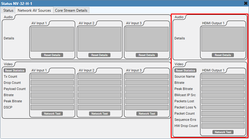
This section only appears when the NV-32-H HDMI I/O Encoder's Properties have HDMI Output Mode set to HDMI 1, and the Mediacast Input Count is set to a value greater than 0.
Audio
The Details section displays cumulative information for HDMI audio being received from the source. This information resets during a design restart on the Q-SYS Core or whenever you click Reset Details.
Video
This section displays cumulative count information for HDMI video being received from a source and transmitted to a display. Information refreshes every second. Click Reset Statistics to clear the information.
- Source Name: The currently-selected AV source being sent to the HDMI output.
- Bitrate: The rolling, averaged video bitrate for the last 1 second of transmission.
- Peak Bitrate: The highest recorded video bitrate for a single frame of video, rounded to the nearest Mbps, since the statistics were reset.
- BMcast IP Src: Bad Multicast IP Source. Displays the source IP addresses that are incorrectly broadcasting on this source's multicast address. (Only one device on the network should be using this multicasting IP address.)
- Packets Lost: Displays how many network packets were lost (due to errors, dropped packets, overruns, etc.) between the currently selected source and this device.
- Packet Loss %: The percentage of network packets lost from the Packet Count.
- Packet Count: The running total of network packets received by the device.
- Sequence Errs: The number of network packets that were received out of order.
- HW Drop Count: The number of network packets successfully retrieved from the network but could not be processed by the NV-32-H hardware.
- Network Test: Click this button to initiate a test of the network's ability to losslessly carry video data from an NV-32-H Encoder to an NV-32-H Decoder (or, in the case of a multicast configuration, multiple Decoders). You can initiate the test from the NV-32-H Status component of either the Encoder or Decoder.
- When you click the button, the Encoder generates a green, pixelated test pattern that should be visible on the display connected to the Decoder. This test pattern causes the NV-32-H Encoder to create an IP video stream that reaches and sustains the Bitrate (Mbps) setting of the HDMI I/O (NV-32-H) Encoder component.
- While the test runs, observe the Decoder's video statistics within the Network AV Sources > Video section. Lost packets, errors, and drops should be at or near 0.
- If you do not see a test pattern, or you see a test pattern but the Decoder's video statistics indicate lost packets, errors, or drops, the network may not be configured properly or is otherwise unable to transport the desired video bitrate. Refer to the Q-SYS Networking > Clocking, Audio, Video, & Control topic to learn about the requirements for Q-SYS Video.
- Click the Network Test button again to end the test, which resumes the AV signal for the HDMI Input.
Note: Do not initiate a Network Test while the system is in use. Running a Network Test disrupts the AV signals being transmitted between Encoder and Decoder, as well as local HDMI output from an Encoder. For long term testing, you should unplug all HDMI sources. The only way to stop the test is to click the Network Test button again.
Decoder
This tab reports the audio and video details and statistics for any HDMI Output on the NV-32-H connected to a Generic HDMI Display.
Audio
The Details section displays cumulative information for HDMI audio being sent to a display. This information resets during a design restart on the Q-SYS Core or whenever you click Reset Details.
Video
This section displays cumulative count information for HDMI video being received from a source and transmitted to a display. Information refreshes every second. Click Reset Statistics to clear the information.
- Source Name: The currently-selected AV source being sent to the HDMI output.
- Bitrate: The rolling, averaged video bitrate for the last 1 second of transmission.
- Peak Bitrate: The highest recorded video bitrate for a single frame of video, rounded to the nearest Mbps, since the statistics were reset.
- BMcast IP Src: Bad Multicast IP Source. Displays the source IP addresses that are incorrectly broadcasting on this source's multicast address. (Only one device on the network should be using this multicasting IP address.)
- Packets Lost: Displays how many network packets were lost (due to errors, dropped packets, overruns, etc.) between the currently selected source and this device.
- Packet Loss %: The percentage of network packets lost from the Packet Count.
- Packet Count: The running total of network packets received by the device.
- Sequence Errs: The number of network packets that were received out of order.
- HW Drop Count: The number of network packets successfully retrieved from the network but could not be processed by the NV-32-H hardware.
- SRC- : The number of incremental video frames that have been dropped on the HDMI output in order to keep the output timing constant.
- SRC+ : The number of incremental video frames that have been repeated on the HDMI output in order to keep the output timing constant.
- Network Test: Click this button to initiate a test of the network's ability to losslessly carry video data from an NV-32-H Encoder to an NV-32-H Decoder (or, in the case of a multicast configuration, multiple Decoders). You can initiate the test from the NV-32-H Status component of either the Encoder or Decoder.
- When you click the button, the Encoder generates a green, pixelated test pattern that should be visible on the display connected to the Decoder. This test pattern causes the NV-32-H Encoder to create an IP video stream that reaches and sustains the Bitrate (Mbps) setting of the HDMI I/O (NV-32-H) Encoder component.
- While the test runs, observe the Decoder's video statistics within the Network AV Sources > Video section. Lost packets, errors, and drops should be at or near 0.
- If you do not see a test pattern, or you see a test pattern but the Decoder's video statistics indicate lost packets, errors, or drops, the network may not be configured properly or is otherwise unable to transport the desired video bitrate. Refer to the Q-SYS Networking > Clocking, Audio, Video, & Control topic to learn about the requirements for Q-SYS Video.
- Click the Network Test button again to end the test, which resumes the AV signal for the HDMI Input.
Note: Do not initiate a Network Test while the system is in use. Running a Network Test disrupts the AV signals being transmitted between Encoder and Decoder, as well as local HDMI output from an Encoder. For long term testing, you should unplug all HDMI sources. The only way to stop the test is to click the Network Test button again.
Core Stream Details
This tab appears only when your design requires NV-32-H audio to be processed by the Q-SYS Core. This information resets during a design restart on the Q-SYS Core or whenever you click Reset Details.
Input Details (Audio to Core)
If audio is being passed to the Q-SYS Core from the NV-32-H, details for that audio appear here, such as when any of these component output audio pins are wired in the design:
- Mic/Line In (NV-32-H)
- HDMI I/O (NV-32-H) – HDMI Channel Audio pins
- Generic AV Source – Breakaway Channel pins
- USB Audio Bridge – Speakerphone / Sound Card In
Output Details (Audio from Core)
If audio is being passed from the Q-SYS Core to the NV-32-H, details for that audio appear here, such as when any of these component input audio pins are wired in the design:
- Line Out (NV-32-H)
- Generic HDMI Display – Breakaway Channel pins
- USB Audio Bridge – Speakerphone / Sound Card Out
USB Bridging Details
This tab appears only if you are using the USB Bridging capabilities (video or audio) of the NV-32-H.
USB Audio
Connection
LED glows green when the USB Out component is connected to a computer.
USB Speed
The speed of the USB connection – for example, "High (2.0)".
Active
LED glows green when the USB audio signal is streaming.
USB Video
Note: To see the data in these fields, you must have a network connection between a Q-SYS camera and the NV-32-H, as well as a USB connection to a computer. The computer must be receiving and displaying the video. If there is no signal flow, there are no statistics.
Input
Input LED
Indicates whether or not there is active input to the Q-SYS video input device.
Input Connection
The network name of the Q-SYS video input device.
Bitrate (Kb/s)
The current input video bitrate, in kilobits per second.
Frames per Sec
Number of frames per second being sent by the video device.
Frame Count
Total number of frames sent.
Packet Count
Total number of packets since the last reset.
Packets Lost
Number of packets lost since the last reset.
Packet Loss%
The percentage of packets lost based on Packets Lost and Packet Count.
Test Button
Test the network setup for the Q-SYS video streaming implementation without having a PC or any USB connection. This tests QoS and IGMP on multicast.
USB
USB Active LED
Video Bridge USB Active: Indicates if the USB is active or not.
USB Bridge Name
The network name of the Q-SYS video bridging device.
Video Format
Displays the format of the video present on the USB – for example, "1920x1080p30".
Encoding
Displays the type of encoding used for the USB video stream - for example, "MJPEG".
USB Speed
Displays the detected USB speed capability of the connection – for example, "High Speed (2.0)".
Bitrate (Mb/s)
USB bitrate, in megabits per second.
Frames per Sec
USB frames per second
SRC-
The number of samples removed in order to match the USB clock with the Q-SYS PTP clock
SRC+
The number of samples added in order to match the USB clock with the Q-SYS PTP clock
Reset
Reset Button
Clears the readings, and restarts monitoring.
Control Pins
The control pins shown depend on whether the NV-32-H is configured as an Encoder or Decoder, as well as the additional components present in the Schematic.
Encoder
|
Pin Name |
Value |
String |
Position |
Pins Available |
|---|---|---|---|---|
|
Core Networked Audio |
||||
|
Input Stream Details |
(text) |
Output |
||
|
Output Stream Details |
(text) |
Output |
||
|
Reset Details |
0 1 |
false true |
0 1 |
Input / Output |
|
Network |
||||
|
Clocking |
||||
|
Grandmaster Name |
(text) |
Output |
||
|
Offset From Master |
- |
nus |
- |
Output |
|
Parent Port Name |
(text) |
Output |
||
|
LAN A |
||||
|
Active |
0 1 |
false true |
0 1 |
Output |
|
IP Address |
(text) |
Output |
||
|
Mode |
(text) |
Output |
||
|
PTP State |
(text) |
Output |
||
|
Speed |
(text) |
Output |
||
|
Networked Audio |
||||
|
|
||||
|
Details |
(text) |
Output |
||
|
Reset Details |
0 1 |
false true |
0 1 |
Input / Output |
|
Networked Video |
||||
|
|
||||
|
Bitrate |
n |
n |
- |
Output |
|
Drop Count |
n |
n |
- |
Output |
|
DSCP |
n |
n |
- |
Output |
|
Network Test |
0 1 |
false true |
0 1 |
Input / Output |
|
Payload Count |
n |
n |
- |
Output |
|
Peak Bitrate |
n |
n |
- |
Output |
|
Tx Count |
n |
n |
- |
Output |
|
USB Speakerphone / Sound Card In |
||||
|
Active |
0 1 |
false true |
0 1 |
Output |
|
USB Speakerphone / Sound Card Out |
||||
|
Active |
0 1 |
false true |
0 1 |
Output |
|
Video Bridge |
||||
|
IP Stream n |
||||
|
Bitrate |
n.n |
n.n |
- |
Output |
|
FPS |
n |
n |
- |
Output |
|
Frame Count |
n |
n |
- |
Output |
|
Packet Count |
n |
n |
- |
Output |
|
Packet Loss Percentage |
n.n |
n.n |
- |
Output |
|
Packets Lost |
n |
n |
- |
Output |
|
Test Stream 1, 2 |
0 1 |
false true |
0 1 |
Input / Output |
|
USB |
||||
|
Active |
0 1 |
false true |
0 1.00 |
Output |
|
Bitrate |
0.0000 and up |
0 and up |
0.00 to 1.00 |
Output |
|
Bridge Name |
(text) |
Output |
||
|
Encoding |
(text) |
Output |
||
|
FPS |
0 to 30 |
0 to 30 | 0.00 to 1.00 |
Output |
|
SRC- |
0 and up |
0 and up |
0.00 to 1.00 |
Output |
|
SRC+ |
0 and up |
0 and up |
0.00 to 1.00 |
Output |
|
USB Speed |
(text) |
Output |
||
|
Video Format |
(text) |
Output |
||
|
Input Active |
0 1 |
false true |
0 1 |
Output |
|
Input Connection |
(text) |
Output |
||
|
Reset |
(trigger) |
Input / Output |
||
|
Aux Power Active |
0 1 |
false true |
0 1 |
Output |
|
CPU Temperature |
n.n |
n.n°C | - |
Output |
|
Fan 1, 2 RPM |
n |
n |
- |
Output |
|
I/O Temperature |
n.n |
n.n°C | - |
Output |
|
Identify |
0 1 |
false true |
0 1 |
Input / Output |
|
Networked Video Reset Statistics |
0 1 |
false true |
0 1 |
Input / Output |
|
NV-32-H Status |
0 1 2 3 4 5 |
OK (Green) Compromised (Orange) Fault (Red) Not Present (Gray) Missing (Red) Initializing (Blue) |
- |
Output |
|
PoE < 90w |
0 1 |
false true |
0 1 |
Output |
|
PoE = 90w |
0 1 |
false true |
0 1 |
Output |
|
USB Connected |
0 1 |
false true |
0 1 |
Output |
|
USB Speed |
(text) |
Output |
||
|
USB Reset |
0 1 |
off on |
0 1 |
Input / Output |
|
VPU Temperature |
n.n | n.n°C | - |
Output |
Decoder
|
Pin Name |
Value |
String |
Position |
Pins Available |
|---|---|---|---|---|
|
Core Networked Audio |
||||
|
Input Stream Details |
(text) |
Output |
||
|
Output Stream Details |
(text) |
Output |
||
|
Reset Details |
0 1 |
false true |
0 1 |
Input / Output |
|
Network |
||||
|
Clocking |
||||
|
Grandmaster Name |
(text) |
Output |
||
|
Offset From Master |
- |
nus |
- |
Output |
|
Parent Port Name |
(text) |
Output |
||
|
LAN A |
||||
|
Active |
0 1 |
false true |
0 1 |
Output |
|
IP Address |
(text) |
Output |
||
|
Mode |
(text) |
Output |
||
|
PTP State |
(text) |
Output |
||
|
Speed |
(text) |
Output |
||
|
Networked Audio |
||||
|
HDMI Output n |
||||
|
Details |
(text) |
Output |
||
|
Reset Details |
0 1 |
false true |
0 1 |
Input / Output |
|
Networked Video |
||||
|
HDMI Output 1, 2 |
||||
|
Bitrate |
n |
n |
- |
Output |
|
BMcast IP Src |
(text) |
Output |
||
|
HW Drop Count |
n |
n |
- |
Output |
|
Network Test |
0 1 |
false true |
0 1 |
Input / Output |
|
Packet Count |
n |
n |
- |
Output |
|
Packet Loss % |
n |
n.n |
- |
Output |
|
Packets Lost |
n |
n |
- |
Output |
|
Peak Bitrate |
n |
n |
- |
Output |
|
Sequence Errors |
n |
n |
- |
Output |
|
Source |
(text) |
Output |
||
|
USB Speakerphone / Sound Card In |
||||
|
Active |
0 1 |
false true |
0 1 |
Output |
|
USB Speakerphone / Sound Card Out |
||||
|
Active |
0 1 |
false true |
0 1 |
Output |
|
Video Bridge |
||||
|
IP Stream 1, 2 |
||||
|
Bitrate |
n.n |
n.n |
- |
Output |
|
FPS |
n |
n |
- |
Output |
|
Frame Count |
n |
n |
- |
Output |
|
Packet Count |
n |
n |
- |
Output |
|
Packet Loss Percentage |
n.n |
n.n |
- |
Output |
|
Packets Lost |
n |
n |
- |
Output |
|
Test Stream 1, 2 |
0 1 |
false true |
0 1 |
Input / Output |
|
USB |
||||
|
Active |
0 1 |
false true |
0 1.00 |
Output |
|
Bitrate |
0.0000 and up |
0 and up |
0.00 to 1.00 |
Output |
|
Bridge Name |
(text) |
Output |
||
|
Encoding |
(text) |
Output |
||
|
FPS |
0 to 30 |
0 to 30 | 0.00 to 1.00 |
Output |
|
SRC- |
0 and up |
0 and up |
0.00 to 1.00 |
Output |
|
SRC+ |
0 and up |
0 and up |
0.00 to 1.00 |
Output |
|
USB Speed |
(text) |
Output |
||
|
Video Format |
(text) |
Output |
||
|
Input Active |
0 1 |
false true |
0 1 |
Output |
|
Input Connection |
(text) |
Output |
||
|
Reset |
(text |
Input / Output |
||
|
Aux Power Active |
0 1 |
false true |
0 1 |
Output |
|
Clock Grandmaster Name |
(text) |
Output |
||
|
Clock Offset from Master |
- | nus | - |
Output |
|
Clock Parent Port Name |
(text) |
Output |
||
|
CPU Temperature |
n.n |
n.n°C | - |
Output |
|
Fan 1, 2 RPM |
n |
n |
- |
Output |
|
I/O Temperature |
n.n |
n.n°C | - |
Output |
|
Identify |
0 1 |
false true |
0 1 |
Input / Output |
|
Networked Video Reset Statistics |
0 1 |
false true |
0 1 |
Input / Output |
|
NV-32-H Status |
0 1 2 3 4 5 |
OK (Green) Compromised (Orange) Fault (Red) Not Present (Gray) Missing (Red) Initializing (Blue) |
- |
Output |
|
PoE < 90w |
0 1 |
false true |
0 1 |
Output |
|
PoE = 90w |
0 1 |
false true |
0 1 |
Output |
|
USB Connected |
0 1 |
false true |
0 1 |
Output |
|
USB Speed |
(text) |
Output |
||
|
USB Reset |
0 1 |
off on |
0 1 |
Input / Output |
|
VPU Temperature |
n.n | n.n°C | - |
Output |
Troubleshooting
Status: "Missing - Insufficient PoE power"
If you are not using a 48V DC (Aux) power supply and are instead powering the NV-32-H using Power over Ethernet, the port to which the NV-32-H is connected must support PoE++ (802.3bt Type 4). The PoE and PoE+ standards are not supported. If you see this status, it means that the switch port either does not support PoE++ (802.3bt Type 4) or cannot properly negotiate this standard. If you are certain that the network switch power supply provides adequate power, you can enable the Operate with any PoE Power Sourcing Equipment option in Peripheral Manager > Network Settings to force the NV-32-H to boot and run with the detected PoE capability.
Note: The NV-32-H checks for proper power only once at startup. If you change your switch PoE settings, you must reboot the NV-32-H so it can check for proper PoE power again.