Status (Sennheiser TCC M Plus)
This topic covers the Device Properties, as well as the Status Component Controls and Control Pins for the Sennheiser TeamConnect Ceiling Medium (TCC M) Plus in Q-SYS Designer.
The Sennheiser TCC M Plus integrates into Q-SYS Designer as a component. No Q-SYS control feature license (i.e., no plugin license) is required. All AES67 stream configuration is handled transparently within the design. It can be found in the Inventory, under Audio - Other.
The Quick Start for configuring the Sennheiser TCC M Plus as a Component in Q-SYS Designer can be found here: Quick Start | Sennheiser TCC M Plus as a Designer Component
Tip: For additional properties that are not listed, refer to the Properties Panel help topic for more information.
Name
The Name may contain ASCII letters 'a' through 'z' (case-insensitive), the digits '0' through '9', and the hyphen. Names cannot begin or end with a hyphen. No other symbols, punctuation characters, or blank spaces are permitted.
Location
User-defined name that groups the component with other components in the same physical location, or in the same organizational scheme.
Is Required
When enabled, and the device is not found on the network, the device is reported as 'Missing', which is an error condition. This is the default behavior. When disabled, and the device is not found on the network, the device is reported as 'Not Present', which is not an error condition.
Dynamically Paired
Indicates that this virtual component can be paired with the same type of hardware without changing the network ID of the hardware or the name of this component. Refer to the Q-SYS Core Manager Dynamic Pairing topic for more information. The default is 'No'.
Installation Type
Dropdown to specify the microphone installation type. Flush mount is used for in or on ceiling installations and suspended mount is used otherwise for optimal acoustic performance.
Selections:
Flush Mounted
Surface Mounted
Suspended
Verbose
Provides additional audio stream info similar to native peripheral status components. Some Control Pins can only be made available when set to Yes. Default is No.
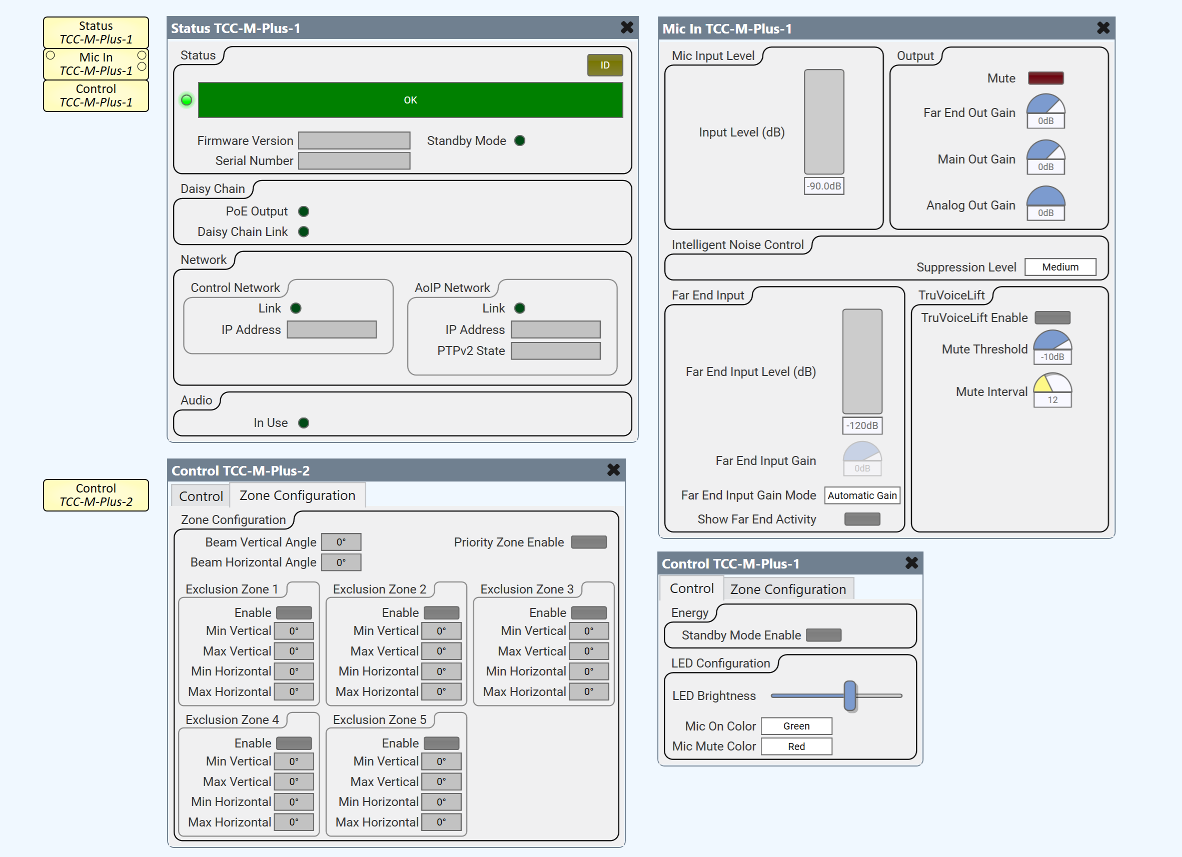
Status
ID
When the ID / Identify button, in the Q-SYS Designer Status component, or the Configurator's Network Configuration for the hardware, or on the physical hardware is pressed, the ID buttons in the Configurator and Status component flash, and the LCD on the physical Hardware flashes to indicate the association between the three.
The indicators will flash for 5 minutes unless you stop them by pressing any one of the buttons.
Status LED
This LED changes color to indicate the current status of the device. See Status for the meanings of the various colors.
Status
Component status is conveyed with the Status LED and Status box, which uses both color and text to indicate the current condition:
- OK: The device is functioning normally.
- Initializing: The device is in the process of a firmware, patch, or configuration update, or the design is starting.
- Compromised: The device is functioning, but a non-fatal problem exists. Refer to the Status box for details.
- Missing: The device cannot be discovered.
- Fault: The device is malfunctioning or is not properly configured. Refer to the Status box for details.
- Unknown: This status appears during a Core reboot (for example, during a firmware update), or when a design is being uploaded to the Core and before it has started running.
- Not Present: If applicable to the device, this status appears when the device is not connected to the network and its Is Required component property is set to 'No'. This status also appears if the device component's Dynamically Paired property is set to 'Yes', pairing has not been assigned in Core Manager, and the device component's Is Required property is set to 'Yes'. See Dynamic Pairing.
Firmware Version
Displays the current firmware version of the device.
Serial Number
Displays the serial number string of the device.
Standby Mode
LED to indicate whether Standby mode is active.
Daisy Chain
PoE Output
LED to indicate whether daisy chain PoE power output is active.
Daisy Chain Link
LED to indicate the link status of the connection at the daisy chain port.
Network
Control Network - Link
LED to indicate whether the control network connection is active and functioning properly.
Control Network - IP Address
Displays the control network IP address.
AoIP Network
AoIP Network -Link
LED to indicate whether the AoIP network connection is active and functioning properly.
AoIP Network - IP Address
Displays the AoIP IP address of the device.
AoIP Network - PTPv2 State
Displays the role of the network device.
Audio
In Use
LED to indicate whether the microphone is in use (i.e., detecting audio).
Audio Stream
(Displayed when Verbose property is set to Yes.)
Input OK
LED to indicate whether input stream is OK. (Displayed when Verbose property is set to Yes.)
Input Details
Displays input stream details. (Displayed when Verbose property is set to Yes.)
Output OK
LED to indicate whether output stream is OK. (Displayed when Verbose property is set to Yes.)
Output Details
Displays output stream details. (Displayed when Verbose property is set to Yes.)
Reset Stream Details
Trigger button to reset the stream details. (Displayed when Verbose property is set to Yes.)
| Pin Name | Value | String | Position | Pins Available |
| Identify |
0 1 |
false true |
0 1 |
Input / Output |
| TCC M Plus Status |
0 1 2 3 4 5 |
OK (Green) Compromised (Orange) Fault (Red) Not Present (Gray) Missing (Red) Initializing (Blue) |
N / A | Output |
| Firmware Version | Text display | Output | ||
| Serial Number | Text display | Output | ||
| Standby Mode |
0 1 |
false true |
0 1 |
Output |
| Daisy Chain - PoE Output |
0 1 |
false true |
0 1 |
Output |
| Daisy Chain - Link |
0 1 |
false true |
0 1 |
Output |
| Network - Control Network - Active |
0 1 |
false true |
0 1 |
Output |
| Network - Control Network - IP Address | Text display | Output | ||
| Network - Control Network - Speed | Text display | Output | ||
| Network - Control Network - PTPv2 Stae | Text display | Output | ||
| Network - AoIP Network - Active |
0 1 |
0 1 |
Output | |
| Network - AoIP Network - IP Address | Text display | Output | ||
| In Use |
0 1 |
0 1 |
Output | |
| Input OK |
0 1 |
0 1 |
Output | |
| Input Details | Text display | Output | ||
| Output OK |
0 1 |
0 1 |
Output | |
| Output Details | Text display | Output | ||
| Reset Stream Details |
0 1 |
0 1 |
Input / Output | |