Control (Sennheiser TCC M Plus)
Use the Control component to configure the Sennheiser TCC M Plus ceiling microphone.
Tip: For additional properties that are not listed, refer to the Properties Panel help topic for more information.
Name
The Name may contain ASCII letters 'a' through 'z' (case-insensitive), the digits '0' through '9', and the hyphen. Names cannot begin or end with a hyphen. No other symbols, punctuation characters, or blank spaces are permitted.
Location
User-defined name that groups the component with other components in the same physical location, or in the same organizational scheme.
Is Required
When enabled, and the device is not found on the network, the device is reported as 'Missing', which is an error condition. This is the default behavior. When disabled, and the device is not found on the network, the device is reported as 'Not Present', which is not an error condition.
Dynamically Paired
Indicates that this virtual component can be paired with the same type of hardware without changing the network ID of the hardware or the name of this component. Refer to the Q-SYS Core Manager Dynamic Pairing topic for more information. The default is 'No'.
Installation Type
Dropdown to specify the microphone installation type. Flush mount is used for in or on ceiling installations and suspended mount is used otherwise for optimal acoustic performance.
Selections:
Flush Mounted
Surface Mounted
Suspended
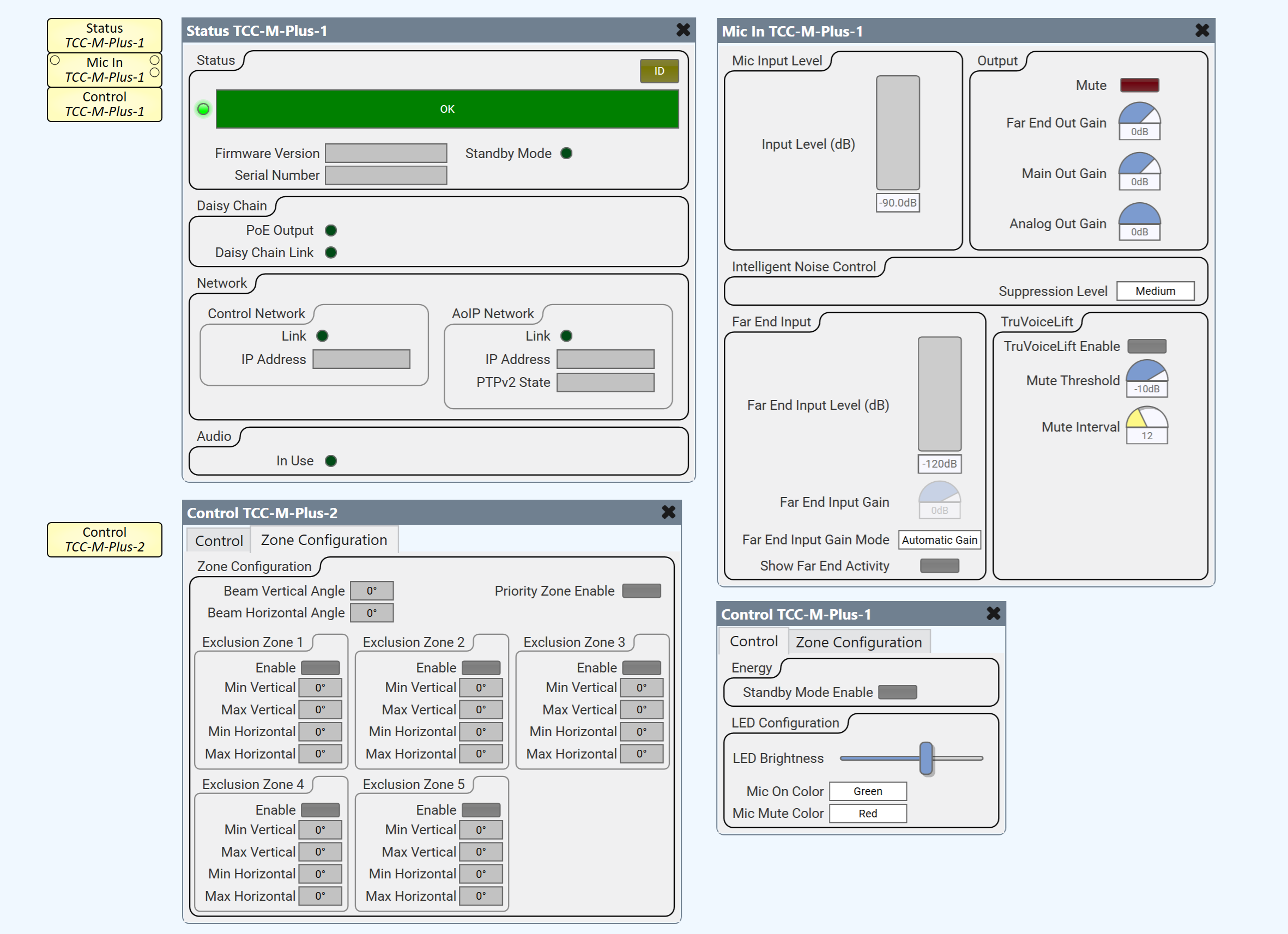
Control
| Control - Energy | ||
| Control | Function | Default / Range |
| Standby Mode Enable | Toggle button to enable / disable Standby mode. | On / Off Default is Off |
| Control - LED Configuration | ||
| Control | Function | Default / Range |
| LED Brightness | Slider to control LED brightness of the device. | 0 1 2 3 4 5 |
| Mic On Color | Dropdown to select Mic On LED color. |
Light Green
Green Red Blue Yellow Orange Cyan Pink (Default is Green) |
| Mic Mute Color | Dropdown to select Mic Mute LED color. | Light Green
Green Red Blue Yellow Orange Cyan Pink (Default is Red) |
| Zone Configuration | ||
| Control | Function | Default / Range |
| Beam Vertical Angle | Displays the vertical angle of the beam direction. | 0° to 90° |
| Beam Horizontal Angle | Displays the horizontal angle of the beam direction. | 0° to 360° |
| Priority Zone Enable | Toggle button to enable / disable the priority zone. | Off / On
Default is Off |
| Zone Configuration - Exclusion Zones 1 - 5 (identical) | ||
| Control | Function | Default / Range |
| Enable | Toggle button to enable / disable Exclusion Zone n. | Off / On
Default is Off |
| Min Vertical | Text display of minimum vertical angle (degrees) of Exclusion Zone n. | 0° to 90° |
| Max Vertical | Text display of maximum vertical angle (degrees) of Exclusion Zone n. | 0° to 90° |
| Min Horizontal | Text display of minimum horizontal angle (degrees) of Exclusion Zone n. | 0° to 360° |
| Max Horizontal | Text display of maximum horizontal angle (degrees) of Exclusion Zone n. | 0° to 360° |
| LED | ||||
| Pin Name | Value | String | Position | Pins Available |
| Brightness | 0 to 5 | 0 to 5 | 0 to 1.00 | Input / Output |
| Mic Mute Color | 0 1 2 3 4 5 6 7 |
Light Green
Green Red Blue Yellow Orange Cyan Pink |
0 to 1.00 | Input / Output |
| Mic On Color | 0 1 2 3 4 5 6 7 |
Light Green
Green Red Blue Yellow Orange Cyan Pink |
0 to 1.00 | Input / Output |
| Zones (Pins for Exclusion Zones 1 - 5 are identical) | ||||
| Pin Name | Value | String | Position | Pins Available |
| Enable | 0 1 |
false true |
0 1 |
Input / Output |
| Minimum Vertical Angle | 0 to 90 | 0° to 90° | 0 to 1.00 | Output |
| Maximum Vertical Angle | 0 to 90 | 0° to 90° | 0 to 1.00 | Output |
| Minimum Horizontal Angle | 0 to 360 | 0° to 360° | 0 to 1.00 | Output |
| Maximum Horizontal Angle | 0 to 360 | 0° to 360° | 0 to 1.00 | Output |
| Priority Zone Enable (Note: One pin for all zones) |
0 1 |
false true |
0 1 |
Input / Output |
| Zone Configuration and Reboot | ||||
| Pin Name | Value | String | Position | Pins Available |
| Beam Vertical Angle | 0 to 90 | 0° to 90° | 0 to 1.00 | Output |
| Beam Horizontal Angle | 0 to 360 | 0° to 360° | 0 to 1.00 | Output |
| Reboot
(Note: Per Q-SYS precedence, the Reboot control pin is only available as a control pin - not present in the component’s control panel UI.) |
0 1 |
false true |
0 1 |
Input / Output |
| Standby Mode Enable | 0 1 |
false true |
0 1 |
Input / Output |