Matrix Mixer
The Matrix Mixer Component is modeled after a standard analog mixer both in appearance and operation. The Matrix Mixer is scalable, and flexible, so you can customize the Matrix Mixer both in size and in function to meet your needs. Or you can have multiple Matrix Mixers for a variety of needs.
The Matrix Mixer size ranges from 1x1 to 512x512 mono channels, or 256x256 stereo channels. You can have both mono and stereo channels in the same Matrix Mixer, as long as the total ((mono + (2*stereo)) does not exceed 512. The Matrix Mixer provides up to 16 VCA groups, four different panning options, and customizable Control Banks for input and output controls, to make working with large Matrix Mixers easier.
Note: Click one of the links to go to the Properties and Control Pins tables.
Note: The number of signal pins is variable and set in the component's Input Count and Output Count Property.
Input Pins
Channels
Audio signal pins are represented by a ( ) circle, and traditional wiring is represented by a thin black line. You can use Signal Names on audio signal pins.
By default, the Matrix Mixer component is set to 8 Mono channels, which provides 8 inputs and 8 outputs. Additionally, you can set the Properties to allow for Stereo, which gives you a Left and Right Audio Channel per input or output count. This will allow you to choose between 2 and 256 inputs and outputs.
Output Pins
Channels
Audio signal pins are represented by a () circle, and traditional wiring is represented by a thin black line. You can use Signal Names on audio signal pins.
By default, the Matrix Mixer component is set to 8 Mono channels, which provides 8 inputs and 8 outputs. Additionally, you can set the Properties to allow for Stereo, which gives you a Left and Right Audio Channel per input or output count. This will allow you to choose between 2 and 256 inputs and outputs.
Tip: For additional properties that are not listed, refer to the Properties Panel help topic for more information.
Matrix Mixer Properties
Input Count
Mono
Sets the number of Input channels. The default Input count is 8 Mono and 0 Stereo.
Stereo
Sets the number of Input Stereo channels. The Mono plus Stereo total cannot exceed 512.
Output count
Mono
Sets the number of Output channels. The default Input count is 8 Mono and 0 Stereo.
Stereo
Sets the number of Input and Output Stereo channels. The Mono plus Stereo total cannot exceed 512.
Control Banking
Note: See Rules for Banked Controls.
Input Bank Size
Banks allow you to view larger Matrix Mixers in sections, or Banks, by choosing the number of channels you want in one of the sections.
Input Bank Size sets the number of input channels in one Bank. The system then divides the Matrix Mixer into the number of Banks required for the existing number of channels. If the division is not an equal number of channels per Bank, the remainder of channels is in the last Bank. If there are fewer channels than specified for one Bank, the Bank selector buttons do not display.
The Input Bank selector buttons are displayed horizontally across the top of the Matrix Mixer.
Output Bank Size
The Output Bank selector buttons are displayed vertically down the side of the Matrix Mixer.
Options
Cue Bus Count
The number of Cue channels for each input channel.
VCA Groups
The maximum VCA groups is the number of Mono Inputs + Stereo Inputs up to a maximum of 16.
Pan Controls
Sets the type of Pan control. Available only when at least one of the Input or Output channels is Stereo.
Label Controls
When set to Yes, blank labels are available on the Inputs and Outputs for assigning a user-defined name to each Input or Output.
2-D Matrix Panner
Enables 2-D Matrix Panner mode. The 2-D Matrix Panner appears when there are no Stereo Inputs / Outputs, and this property is set to 'Yes'.
Panner Normalization
Available only when the 2-D Matrix Panner Property is set to Yes.
Constant Voltage: If you take the outputs of the 2-D Matrix Panner and sum them back together with a second mixer, the output of the second mixer is exactly the same as the input to the panner. It also means that if you have one input and two outputs and the input is located exactly between the outputs, the gain applied to each output will be -6dB.
Constant Power: if you sum the power at each output of the panner, it will equal the power at the input to the panner. It also means that if you have one input and two outputs and the input is located exactly between the outputs, the gain applied to each output will be -3dB.
Label Controls
When set to Yes, blank labels are available on the Inputs and Outputs for assigning a user-defined name to each Input or Output.
Crosspoint Mute Controls
Available when the 2-D Matrix Panner Property is set to No.
When set to Yes, this provides a Mute button for each crosspoint.
Cross Solo Controls
Available when the 2-D Matrix Panner Property is set to No.
When set to Yes, this provides a Solo button for each crosspoint, and removes the Input solo buttons.
Crosspoint Gain Type
Select the type of gain to use for the crosspoint:
Standard: (Default) A standard, logarithmic dB gain.
X-Fade -3dB: Special gain type. -3dB is a constant power cross-fade.
X-Fade -6dB: Special gain type. -6dB is a constant voltage cross-fade.
Trim (dB)
Adjusts the sensitivity of the Input signal, and works together with the Gain fader to create the gain structure. For example, you can set the Gain faders at 0 dB and adjust the Trim control in relation to the Gain, giving the Gain fader control in both directions from 0 dB.
Pan per Input
The Pan per Input control can be selected in the Properties when you have at least one stereo Input or Output channel. The Pan knob, for the associated Input channel, pans the input across all Output channels.
A mono input is panned across the stereo left and right output. There is no pan for the mono input to mono output.
A stereo input is panned across a mono output, the left and right stereo signals vary to the mono output.
A stereo input is panned across a stereo output, the left and right signals vary on the left and right outputs respectively.
VCA Group Assignment
Each VCA Group provides one Group Assignment button per channel. For example, three VCA Groups provide three Group Assignment buttons for each channel. To associate an input channel with a VCA Group, click the desired VCA Group Assignment button for the channel.
Cue
Available when the Cue Bus Count is greater than zero as set in Properties.
Each Cue bus provides one audio output that can be sent to other components for processing. The audio output for one Cue bus is collected from the associated input after the Trim control.
Send (Cue)
When engaged, the Send button sends the audio from the associated input to the Cue output.
AFL (Cue)
The AFL (After Fader Level) button determines if the audio for the Cue is taken before or after the Input Gain Fader. The default is PFL (Pre Fader Level) which means the Fader will not change the audio level to the Cue. When the AFL button is engaged, the audio is taken after the Fader, and the Fader level affects the Cue output level.
Mute (Cue)
Mutes the Cue output
Gain (Cue) (dB)
Adjusts the output gain of the Cue channel.
Radius
Available with the 2-D Panner only.
Controls the size of the "circle of influence" an Input Position Control has on the relative gain of the Output Position Controls.
The larger the radius, more Output Position Controls are affected and there is little change when the Input Position Control is moved.
The smaller the radius, fewer Output Position Controls are affected and there is a larger change when the Input Position Control is moved.
Solo
Mutes all of the other Input channels except other channels that have the Solo button engaged. The Solo button takes precedence over the Input or VCA Mute buttons, but not over the Crosspoint Mute button.
Invert
Inverts the input signal for the Input channel. The signal is inverted for all Output channels.
Mute
Mutes the input signal for the Input channel. The signal is muted for all Output channels.
Gain (dB)
The Fader adjusts the gain of the signal for the Input channel. The gain of the Input channel is adjusted for all Output channels.
Nudge + and - Buttons
Allows small, equal adjustments of the Input Fader.
Label
Available when the Label Controls Property is set to yes. These are user-defined labels to easily identify an input or output channel.
Note: The junction between a mono input and a mono output will not have a crosspoint pan control.
Pan per Crosspoint
The Pan per Crosspoint control can be selected in the Properties when you have at least one stereo input or output channel. A Pan knob for an input/output combination, pans the input across the intersected output.
A mono input to mono output does not have a crosspoint Pan knob.
A stereo input left and right signals are panned across a mono output.
Stereo input left and right signals are panned across the left and right stereo output.
Solo
Available when the Crosspoint Solo Controls Option is set to Yes.
The crosspoint Solo button solos the associated Input to the associated Output. The Input Solo button is different in that it solos one Input to all the Outputs. The crosspoint Solo button overrides the Input Mute, VCA Mute, and the crosspoint Mute buttons.
Mute
Available when the Crosspoint Mute Controls Option is set to Yes.
The crosspoint Mute button mutes the associated Input to the associated Output.
Gain
The Crosspoint Gain control adjusts the Input signal (both left and right channels if stereo) after the Crosspoint Pan controls and before the Output.
VCA Group
The VCA Group buttons determine to which VCA Group an Input channel belongs.
2-D Matrix Panner
The 2-D Matrix Panner is available only when there are no stereo channels defined in the Mixer Properties.
There is one Position Control for each Input and each Output defined. Position Controls are numbered to indicate the associated Input/ Output.
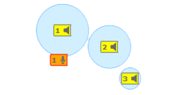
The Output Position Controls are indicated by a loudspeaker icon in a yellow box. ![]()
The Input Position Controls are indicated by a microphone icon in a green box. ![]()
Move the Position Controls around in the pan area to control the relative gain between inputs and outputs. As you move a Position Control, Gain Circles display over the Input or Output Position Controls in different sizes to indicate the relative gain to those Inputs or Outputs. The closer an Input (Output) Position Control is to an Output (Input) Position Control, the larger the Gain Circle.
Label
Available when the Label Controls Property is set to yes. These are user-defined labels to easily identify an input or output channel.
Pre
The default for the Pre/Post button is Post.
In the Post position, all controls operate normally.
In the Pre position, the Input Gain and VCA Gain faders are bypassed for the associated Output channel only. All other controls operate normally.
Invert
Inverts all the Input signals, including left and right stereo channels, to the specific Output channel.
Mute
Mutes all the Input signals, including left and right stereo channels, to the specific Output channel.
Gain (overall per output) (dB)
Adjusts the gain of all the Input signals, including left and right stereo channels, to the specific Output channel.
Mute
Mutes all the input channels associated with that VCA Group.
Gain (dB)
Adjusts the gain for all the input channels associated with that VCA Group.
The available Control Pins depend on settings in Properties.
|
Pin Name |
Value |
String |
Position |
Pins Available |
|---|---|---|---|---|
|
Cue n Gain 1 |
-100 to 10 |
-100 dB to 10 dB |
0.000 1.000 |
Input / Output |
|
Cue n Mute 1 |
0 1 |
unmute mute |
0 1 |
Input / Output |
|
Group n Gain 2 |
-100 to 10 |
-100 dB to 10 dB |
0.000 1.000 |
Input / Output |
| (text) |
Input / Output |
|||
|
Group n Mute 2 |
0 1 |
unmute mute |
0 1 |
Input / Output |
|
Input n Cue n AFL1 |
0 1 |
false true |
0 1 |
Input |
|
Input n Cue n Enable1 |
0 1 |
false true |
0 1 |
Input |
|
Input n Gain |
-100 to 10 |
-100 dB to 10 dB |
0.000 1.000 |
Input / Output |
|
Input n Invert |
0 1 |
normal invert |
0 1 |
Input / Output |
|
Input n Label3 |
(text) |
Input / Output |
||
|
Input n Mute |
0 1 |
unmute mute |
0 1 |
Input / Output |
|
Input n Output n Gain (crosspoint) |
-100 to 10 |
-100 dB to 10 dB |
0.000 1.000 |
Input / Output |
|
Input n Output n Mute 4 (crosspoint) |
0 1 |
unmute mute |
0 1 |
Input / Output |
|
Input n Output n Pan 5 (crosspoint) |
-1.00 to 1.00 |
L100 to R100 |
0.000 to 1.00 |
Input / Output |
|
Input n Output n Solo 6 (crosspoint) |
0 1 |
normal solo |
0 1 |
Output |
|
Input n Pan |
-1.00 to 1.00 |
L100 to R100 |
0.000 to 1.00 |
Input / Output |
|
0.000 to 1.00 |
0.000 to 1.00 |
0.000 to 1.00 |
Input / Output |
|
|
Input n Solo |
0 1 |
normal solo |
0 1 |
Output |
|
Input n Trim |
-12 to 12 |
-12 dB to 12 dB |
0.000 to 1.00 |
Output |
|
Input n VCA Group n Assign 2 |
0 1 |
false true |
0 1 |
Output |
|
Output n Gain |
-100 to 10 |
-100 dB to 10 dB |
0.000 1.000 |
Input / Output |
|
Output n Invert |
0 1 |
normal invert |
0 1 |
Input / Output |
| Output n Label3 | (text) |
Input / Output |
||
|
Output n Mute |
0 1 |
unmute mute |
0 1 |
Input / Output |
|
0.000 to 1.00 |
0.000 to 1.00 |
0.000 to 1.00 |
Input / Output |
|
|
Output n Pre/Post |
0 1 |
post pre |
0 1 |
Input / Output |
1. Available when the Cue Bus Count is greater than zero.2. Available when the VCA Groups Property is greater than zero.3. Available when Label Controls is set to Yes.4. Available when Crosspoint Mute Controls Option is set to Yes.5. Available on Stereo Input to Stereo Output crosspoints when Pan Per Crosspoint is set to Yes.6. Available when Crosspoint Solo Controls Option is set to Yes.7. Available when there are no Stereo Inputs or Outputs and the 2-D Matrix Panner is set to Yes.8. The ‘position’ is an array of two coordinates, ‘x' and a ‘y' whose values both range from 0.000 to 1.000. The pins should only be connected to a “Control Script” component (text controller and block controller don't have pins that are arrays). If you connect directly to the input control pin from another control, for example a position control, it supplies only a single value so only the x coordinate is updated and the position controls in the 2-D Panner only will move horizontally. |
||||
Banked Controls in Snapshot Banks
When the Matrix Mixer has "banked" controls:
- The system will not allow you to place individual controls into a Snapshot Bank.
- You can place the Matrix Mixer component into a Snapshot Bank, and all the controls will work properly.
- You can un-bank the Matrix Mixer component (i.e., set Input and Output Bank Size to 'Not Banked'), add individual controls, then re-bank the Matrix Mixer, and the individual controls will work properly.
Tip: The advantage of placing individual controls into a Snapshot Bank is that when you Load the Snapshot, only those controls are repositioned. Any other controls that have been manually positioned, or positioned by another Snapshot do not change. If all the controls are in a Snapshot Bank, when one of the Snapshots is Loaded, all the controls are positioned as they were Saved in that Snapshot.
Banked Controls in UCIs
When copying Matrix Mixer controls to a User Control Interface (UCI), you must first un-bank the Matrix Mixer (i.e., set Input and Output Bank Size to 'Not Banked'). This ensures that the correct control ID is copied to the UCI. Then, you can re-bank the Matrix Mixer.
- Mono channels are on the left side of the Input bank and the top of the Output bank.
- Stereo channels are on the right side of the Input bank and the bottom of the Output bank.
- Input Channels — Input controls are aligned vertically in the Matrix Mixer Control Panel.
- Crosspoint Controls — The Crosspoint controls are at the junction between an Input channel and an Output channel. The crosspoint Gain and Pan knobs control the input signal going to the intersected output.
- Output Channels are aligned horizontally in the Matrix Mixer Control Panel.
- Gain — The gains are cumulative for the related input and output channels.
- Input Gain — The gain prior to the crosspoint is derived from a combination of the Input Trim, Mute, Invert, Solo, Gain4 controls, and VCA Group Gain and Mute controls of groups in which the input channel is a member 45.
- Crosspoint Gain — The gain after each crosspoint, and prior to the output, is derived from a combination of all the input gains plus the associated Pan 1 2 3 and Gain controls.
- Output Gain — The final output gain of a channel is derived from a combination of all the input controls, the crosspoint controls and the output Gain value, Mute, and Invert buttons.
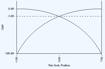
- When the Pan knob is in the center (C, or 0.00) the sound is equal or balanced in the left and right outputs, but at -3 dB below the original input. This is done to keep the overall sound at the same volume when the Pan knob is moved to one side or the other. If the input is stereo, when the Pan knob is fully to one side, the opposite input is completely off and only one stereo channel is heard. If the input is mono, the signal is simply moved from one side to the other.
The Pan Law is to keep the overall volume of two outputs, usually stereo channels, equal as the input is panned from one side to the other.