Flattop Parametric Equalizer
The Flattop Parametric Equalizer component is similar to the standard Parametric Equalizer, but offers asymmetrical filtering for more precision tuning of loudspeaker responses. It is a variable equalizer that allows you to individually adjust the Gain, Bandwidth, center Frequency, and lower and upper transition Bandwidths and Frequencies of up to 32 frequency bands. You can also Bypass individual bands. Master controls, affecting all bands, include Bypass, Invert, Mute and Gain. Additionally, you can change any or all of the bands to either a high or low-shelf equalizer, allowing you to vary the gain of all frequencies, as a group, above or below a selected frequency. At the selected Frequency, the gain changes approximately +3dB or -3dB depending on whether the shelf is adding or reducing gain.
Both lower and upper transition bandwidths and frequencies can all be adjusted independently. This allows for flattop responses with asymmetrical slopes. Responses of adjacent bands with identical gains, transition bandwidths, and frequencies sum perfectly.
The overall equalizer phase response is minimum-phase.
Note: The number of signal pins is variable and set in the component's Type Property.
Input Pins
Channels
Audio signal pins are represented by a ( ) circle, and traditional wiring is represented by a thin black line. You can use Signal Names on audio signal pins.
By default, the Flattop Parametric Equalizer component is set to a Mono channel, which provides one input and one output. Additionally, you can set the Properties to allow for Stereo, which gives you two inputs and outputs; or you can choose Multi-Channel, which will allow you to choose between 2 and 256 inputs and outputs.
Output Pins
Channels
Audio signal pins are represented by a () circle, and traditional wiring is represented by a thin black line. You can use Signal Names on audio signal pins.
By default, the Flattop Parametric Equalizer component is set to a Mono channel, which provides one input and one output. Additionally, you can set the Properties to allow for Stereo, which gives you two inputs and outputs; or you can choose Multi-Channel, which will allow you to choose between 2 and 256 inputs and outputs.
Tip: For additional properties that are not listed, refer to the Properties Panel help topic for more information.
Flattop Parametric Equalizer Properties
Band Count
Sets the number of bands available in the Equalizer, from 1 to 32.
Min Transition Bandwidth
Determines how quickly the response transitions from the non-gain region to the gain region or vice versa. A wide (1 Octave) transition results in less computational resources being used while a narrow (1/12 Octave) transition results in more computational resources being used. If the default option (1/12 Octave) results in resource usage that is too high and if a wider transition bandwidth is acceptable, select a wider option.
Options: 1, 1/2, 1/3, 1/6, 1/12 Octave (default)
Note: The actual transition bandwidth can still be adjusted using the Lower and Upper Bandwidth controls in the control panel.
Channels
Type
Sets the type of input/output channels: Mono, Stereo, or Multi-Channel. Multi-Channel enables the Count property.
Count
Sets the number of input/output channels for Multi-Channel, from 2 to 256.
Response
Enabled
Enables or disables the graphical Response graph.
Size
Sets the size of the graphical Response graph: Small, Medium, Large.
Response
Response Panel
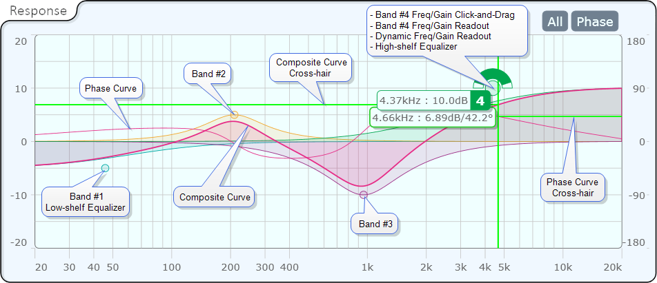
The Response panel provides vertical and horizontal cross-hairs with a dynamic frequency and level read-out. Place the mouse courser over the graph to activate the cross-hairs. When the Phase control is activated, the horizontal cross-hair line to the left of center represents the normal curve, the right side represents the phase curve. The readout is only for the normal curve.
X-Axis = Frequency, 20Hz to 20kHz
Y-Axis Left = dB, -20 to 20
Y Axis Right = Phase, -180° to 180°
All (Bands)
A toggle button that activates a graphical display all bands of the equalizer. When the button is not enabled, the Response Panel displays a composite of all the bands. The composite cannot be turned off.
Phase
Turns the Phase curve display on and off.
Master
Bypass
Click to bypass all bands of the equalizer.
Invert
Click to toggle whether the output signal of the equalizer is inverted or normal.
Mute
Click to mute the output of the equalizer.
Gain
Adjust the overall gain of the equalizer, from -20dB to 20dB (default is 0dB).
Band
Bypass
Click to bypass an individual frequency band.
Frequency
Adjust the Lower, Center, and Upper frequency for each band, from 10.0Hz to 20.0kHz.
Note: The default is different for each band, and depends on number of bands.
Gain
Set the gain for an individual frequency band, from -20dB to 20dB (default is 0dB).
Bandwidth
Set the Lower, Center, and Upper Bandwidth octave value of an individual band of the equalizer, up to 10.0.
Note: The minimum value depends on the Min Transition Bandwidth property. The Center bandwidth octave defaults to 1.00.
Type
Select the type of equalizer for the individual band: Parametric (default), Low-Shelf, or High-Shelf.
|
Pin Name |
Value |
String |
Position |
Pins Available |
|---|---|---|---|---|
|
Band n |
||||
|
Bypass |
0 1 |
no bypassed |
0 1 |
Input / Output |
|
Center Bandwidth |
.083 to 10.0 |
.083oct to 10.0oct |
0.000 to 1.00 |
Input / Output |
|
Center Frequency |
10 to 20000 |
10.0 Hz to 20.0kHz |
0.000 to 1.00 |
Input / Output |
|
Equalizer Type |
1 2 3 |
Parametric Low-shelf High-shelf |
0 0.5 1.00 |
Input / Output |
|
Gain |
-20.0 to 20.0 |
-20.0dB to 20.0dB |
0.000 to 1.00 |
Input / Output |
|
Lower Bandwidth |
.083 to 10.0 |
.083oct to 10.0oct |
0.000 to 1.00 |
Input / Output |
|
Lower Frequency |
10 to 20000 |
10.0 Hz to 20.0kHz |
0.000 to 1.00 |
Input / Output |
|
Lower Gain |
-20.0 to 20.0 |
-20.0dB to 20.0dB |
0.000 to 1.00 |
Input / Output |
|
Upper Bandwidth |
.083 to 10.0 |
.083oct to 10.0oct |
0.000 to 1.00 |
Input / Output |
|
Upper Frequency |
10 to 20000 |
10.0 Hz to 20.0kHz |
0.000 to 1.00 |
Input / Output |
|
Upper Gain |
-20.0 to 20.0 |
-20.0dB to 20.0dB |
0.000 to 1.00 |
Input / Output |
|
Master |
||||
|
Bypass |
0 1 |
no bypassed |
0 1 |
Input / Output |
|
Gain |
-20.0 to 20.0 |
-20.0dB to 20.0dB |
0.000 to 1.00 |
Input / Output |
|
Invert |
0 1 |
normal inverted |
0 1 |
Input / Output |
|
Mute |
0 1 |
unmuted mute |
0 1 |
Input / Output |