Flanger Component
The Flanger mixes two identical signals, with one of the signals delayed by a small, slowly modulated amount. The Flanger produces peaks and notches in the output frequency spectrum, related to one another in a linear harmonic series. Modulating the delay time causes these to sweep up and down the frequency spectrum. The Q-SYS Flanger takes the input signal, splits the signal, delays one of the signals (wet) then mixes it with the other signal (dry) to produce the effect.
The delayed signal is fed back to the delay line at a selectable amount, which produces a resonance effect, enhancing the intensity of the peaks and notches. The phase of the fed-back signal is sometimes inverted, producing another variation on the flanging sound.
Note: The number of signal pins is variable and set in the component's I/O ConfigurationProperty.
Input Pins
Input
Audio signal pins are represented by a ( ) circle, and traditional wiring is represented by a thin black line.
By default, the Flanger Effect component is set to a Mono In / Mono Out, which provides one input. Additionally, you can set the Properties to allow for Mono In / Stereo Out, which gives you one input, or you can set it to Stereo In /Stereo Out which will give you two inputs.
Output Pins
Output
Audio signal pins are represented by a () circle, and traditional wiring is represented by a thin black line.
By default, the Flanger Effect component is set to a Mono In / Mono Out, which provides one output. Additionally, you can set the Properties to allow for Mono In / Stereo Out, which gives you two outputs (Left and Right), or you can set it to Stereo In /Stereo Out which will also give you two outputs (Left and Right).
Tip: For additional properties that are not listed, refer to the Properties Panel help topic for more information.
Flanger Effect Properties
I/O Configuration
Sets the configuration of inputs and outputs for the Flanger component. You can choose Mono In / Mono Out, Mono In / Stereo Out, Stereo In / Stereo Out.
Max Delay (seconds)
Sets the maximum delay allowed for the Delay knob in the component's control panel.
Master Bypass
When engaged, this button bypasses all of the Flanger's controls.
Stereo Spread (%)
Available when the I/O Configuration Property is set to Stereo In/Stereo Out.
Determines the separation spread between the channels. 0% is equal amount of each channel mixed to the other, 100% is complete separation of the channels.
High-Pass Frequency (Hz)
Frequencies below this frequency are attenuated. All frequencies above this frequency are amplified based on the setting of the Gain control.
Low-Pass Frequency (Hz)
Frequencies above this frequency are attenuated. All frequencies below this frequency are amplified based on the setting of the Gain control.
LFO Frequency (Hz)
The frequency at which the LFO produces the waveform, or LFO Shape. The LFO Frequency controls the frequency, or speed, at which the Delay is modulated.
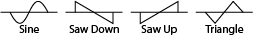
LFO Shape
You can select one of 4 different waveforms.
LFO Stereo Spread (%)
Available when the I/O Configuration Property is set to Mono In/ Stereo Out, or Stereo In/Stereo Out.
In either of the Stereo modes, the LFO produces two synchronized waveforms, one for each channel. The LFO Spread determines the phase shift between these two LFO waveforms. 0% is in phase, 100% is 180° out of phase.
Delay (ms)
- The amount of time the wet signal is delayed from the dry signal.
- The center delay of the modulation, or Depth - the delay time is modulated around this time amount.
- Sets the maximum modulation Depth. If you set the Depth to it's maximum (100 ms) then the Delay amount will control the Depth amount.
Note: Entering anything from 0.001µs to 0.005µs gets interpreted as 1.00 through 5.00 milliseconds. Entering anything greater than 0.005 gets interpreted as the milliseconds as entered (example 0.006 gets interpreted as .006 ms). The basic idea is that the value that you enter is larger than the max value and Q-SYS Designer assumes you want the value to be divided by 1000. If you need to input less than 6ms, you must manually type in ("5us", "4us", etc.). You will then see it convert to .005 ms, .004ms, etc.
Feedback (%)
The amount of delayed signal fed back into the delay line, producing a resonance effect.
Wet Solo
When engaged, allows you to listen to the wet signal by itself.
Wet Gain (dB)
Controls the gain of the wet output.
Dry/Wet Mix (%)
The percentage of wet to dry signal sent to the output. 0% is all dry signal, and no wet. 100% is all wet, and no dry.
The available Control Pins depend on settings in Properties.
|
Pin Name |
Value |
String |
Position |
Pins Available |
|---|---|---|---|---|
|
Delay |
0.000 - 1.00 |
.083ms - 1.00s |
0.00 - 1.00 |
Input / Output |
|
Depth |
0.000 - 1.00 |
.083ms - 1.00s |
0.00 - 1.00 |
Input / Output |
|
Dry/Wet Mix |
0.00 - 100 |
— |
0.00 - 1.00 |
Input / Output |
|
Feedback |
0.00 - 100 |
— |
0.00 - 1.00 |
Input / Output |
|
High-Pass Frequency |
10.0 - 20,000 |
10Hz - 20kHz |
0.00 - 1.00 |
Input / Output |
|
LFO Frequency |
0.010 - 120 |
.010Hz - 120Hz |
0.00 - 1.00 |
Input / Output |
|
LFO Shape |
1 - 4 |
Sine Saw Up Saw Down Triangle |
0 .333 .666 1.00 |
Input / Output |
|
LFO Stereo Spread |
0.00 - 100 |
— |
0.00 - 1.00 |
Input / Output |
|
Low-Pass Frequency |
10.0 - 20,000 |
10Hz - 20kHz |
0.00 - 1.00 |
Input / Output |
|
Master Bypass |
0 1 |
no bypassed |
0 1 |
Input / Output |
|
Wet Gain |
-100 to 20 |
-100 dB to 20 dB |
0.000 to 1.00 |
Input / Output |
|
Stereo Spread |
0.00 - 100 |
— |
0.00 - 1.00 |
Input / Output |
|
Wet Solo |
0 1 |
normal solo |
0 1 |
Input / Output |