AV I/O (NV-21-HU)
Use the AV I/O component to configure AV video and audio routing in Q-SYS as a Shift Encoder, Decoder, or Mediacast Encoder.
NV-21-HU as a Shift Encoder, Decoder, or Mediacast Encoder
For NV-21-HU Network Video Endpoints, the AV I/O component represents a single NV-21-HU device configured as a Shift Encoder or Decoder for sending or receiving AV signals over the network and as of Q-SYS Designer Version 10.4, "Mediacast Encoder" is now included as a Device Type property.
Q-SYS Shift Networked AV Streaming
- A Shift Encoder takes source AV signals and places them on the network in streams. Shift Encoders can process a single stream up to 4K60.
- A Decoder processes incoming network AV signals and sends them to a display. Decoders can process a single stream up to 4K60.
Mediacast Encoder Streaming
- The NV-21-HU can now be configured as a Mediacast Encoder (Device Type = "Mediacast Encoder" in Properties), which ingests HDMI video input and distributes it as Mediacast streams to NVM-302D Decoders within the same Q-SYS design.
- Shift AV streaming is disabled in this mode
- Mediacast Encoder uses multicast streaming automatically — the IP Streaming Mode property is hidden
- The AV I/O component in Mediacast Encoder mode replaces Shift AV Output pins with Mediacast Output pins (up to 2 on NV-21-HU). Each Mediacast output is automatically associated with the corresponding HDMI source — no input selection buttons are exposed
- Mediacast streams from NV-21-HU are currently limited to 1080p30 YUV 4:2:0
Local HDMI Switching
- For Encoders, use HDMI Output 1 as a “courtesy monitor”, displaying at resolutions up to 4K60.
- When set to a decoder and in USB-C operating mode, the HDMI out can show network content or local content from the USB-C input up to 4K60
- For Decoders, toggle between network streams or locally connected AV sources (single 4K60 or dual 1080p60 sources).
USB-C
USB-C cables must meet the following minimum requirements for proper operation with the NV-21-HU:
- Thunderbolt 3 supporting ≥ 65W
- Thunderbolt 4 supporting ≥ 65W
- USB-C 3.2 Gen 1/3.2 and Gen 2 supporting ≥ 65W and DisplayPort Alt Mode (DP 1.4)
- USB4 supporting ≥ 65W
- A USB-C cable and source device must support a minimum of USB superspeed (5Gbps) for AV bridging.
Note: DisplayPort to USB-C cables are not supported.
HDMI
- QSC supports the direct connection between NV Series Video Endpoints and HDMI sources and displays.
- The use of signal extension solutions (for example: HDBaseT extenders, HDMI distribution amps, and active/optical HDMI cables and keystones) and docking stations in-line with NV Series HDMI ports may introduce handshake issues or signal attenuation-related issues. QSC does not test any configurations with these products.
- To maximize HDMI signal reliability, use Premium or Ultra High Speed certified cables.
Note: The input and output pins shown depend on the Q-SYS hardware and component Properties.
Input Pins
 HDMI AV Input
There is one HDMI input on the NV-21-HU. Connect this pin to a Generic AV Source component HDMI AV Output pin.
 USB-C Input
There is one USB-C input on the NV-21-HU.
Output Pins
AV Output 
The AV Output pins send combined video and audio signals over the Q-LAN network. The output correspond to a respective AV Input pin.
HDMI AV Output 1
If enabled in the component Properties (HDMI Output Mode is set to "HDMI 1"), this pin outputs a selectable signal from the one HDMI input on the NV-21-HU. Connect this pin to a Generic HDMI Display HDMI AV Input pin.
Note: The HDMI output supplies up to 120mA on the +5v signal line.
HDMI 1 Channel 1, 2 
If enabled in the component Properties (HDMI Output Mode is set to "HDMI 1"), select the number of audio pins to expose – from 0 to 8 – for routing to other Q-SYS audio components, such as a network amplifier. This audio corresponds to the HDMI Output 1 source you select in the Encoder control panel.
Input Pins
AV Input 1, 2, 3
The AV Input pins receive the combined video and audio signals from the Q-LAN network. Connect an AV Input pin to an AV Output pin on the I/O Encoder component.
HDMI AV Input 1
Each pin represents one of the two HDMI inputs on the NV-21-HU. Connect this pin to a Generic AV Source component HDMI AV Output pin.
Output Pins
HDMI AV Output 1
This pin output a selectable signal from any of the AV I/O inputs, including the AV inputs and local HDMI inputs. Connect this pin to a Generic HDMI Display HDMI AV Input pin. By default, a single HDMI AV output pin is exposed.
Note: Each HDMI output supplies up to 120mA on the +5v signal line.
HDMI 1, 2 Channel 1, 2
If enabled in the component Properties (HDMI Output Mode is set to "HDMI 1 + HDMI 2"), select the number of audio pins to expose – from 0 to 8 – for routing to other Q-SYS audio components, such as a network amplifier. This audio corresponds to the HDMI Output 1 or 2 source you select in the Decoder control panel.
Tip: These pins automatically send audio for whatever HDMI video source is selected for display. No additional programming is required to align audio and video signals.
Input Pins
HDMI AV Input 1
There is one HDMI input on the NV-21-HU. Connect this pin to a Generic AV Source component HDMI AV Output pin.
USB-C Input
There is one USB-C input on the NV-21-HU.
Output Pins
Mediacast Output 1 
Primary encoded Mediacast stream output. This output correspond to a respective HDMI AV Input 1.
Mediacast Output 2
Second Mediacast stream output. This output correspond to a respective USB-C Input.
HDMI AV Output 1
If enabled in the component Properties (HDMI Output Mode is set to "HDMI 1"), this pin outputs a selectable signal. Connect this pin to a Generic HDMI Display HDMI AV Input pin. The HDMI output supplies up to 120mA on the +5v signal line.
HDMI 1 Channel 1, 2
If enabled in the component Properties (HDMI Output Mode is set to "HDMI 1"), select the number of audio pins to expose — from 0 to 8 — for routing to other Q-SYS audio components, such as a network amplifier.
Camera Output
Note: Mediacast Streams are always multicast.
In this example, a single display is being used in a small conference room.
In this example, Room B is acting as an overflow for Room A. This design is using NV-21-HU as an Encoder and NV-32-H as a Decoder.

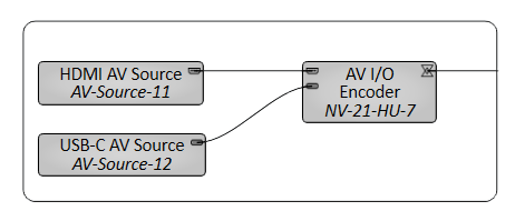
In this example, two inputs are multiplexed onto one output stream in the Encoder.
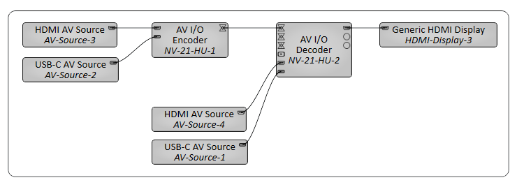
In this example, the room contains an HDMI AV source, and a USB-C AV Source. Each can display a separate network AV source.
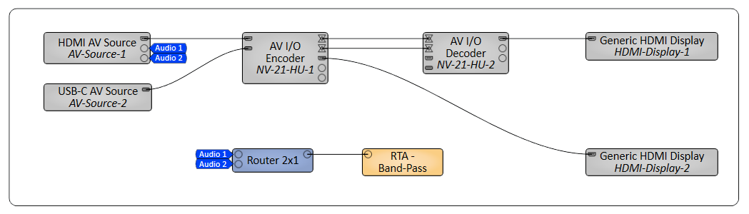
Tip: You can also route audio to a display by exposing audio input pins for that display. This can be useful, for example, for inserting audio from a Q-SYS PA system (pages) for output on a display's internal speakers or a connected speaker bar. For more information, and to see an example, see Generic HDMI Display.
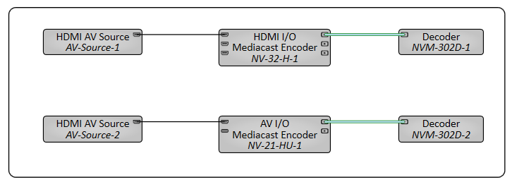
In this example, an NV-21-HU is configured as a Mediacast Encoder. An HDMI source is connected to the NV-21-HU, which encodes the video and sends it as a Mediacast stream to an NVM-302D Decoder. Set the NVM-302D's Properties > Mediacast > Input Count to at least "1".
Tip: For additional properties that are not listed, refer to the Properties Panel help topic for more information.
HDMI / Shift AV
Device Type
Can set the NV-21-HU as a Decoder, Shift Encoder, or Mediacast Encoder.
AV Input Count
For Decoders only, this property determines the number of exposed AV input pins, from 0 to 480. The default is '3'.
HDMI Output Mode
This property determines the functionality of the NV-21-HU HDMI outputs.
HDMI 1: Video and audio output is enabled for the HDMI 1 output connector.
HDMI 1 Audio Pins
If enabled in the component Properties (HDMI Output Mode is set to "HDMI 1 + HDMI 2"), select the number of audio pins to expose – from 0 to 8 – for routing to other Q-SYS audio components, such as a network amplifier. This audio corresponds to the HDMI Output 1 or 2 source you select in the HDMI I/O control panel.
Tip: These pins automatically send audio for whatever HDMI video source is selected for display. No additional programming is required to align audio and video signals.
AV IP Streaming
For Encoders only, this property determines the network streaming method for Q-LAN AV streams:
- Compiler Choice: (Default) Select this option to allow Q-SYS Designer Software to determine whether unicast (one-to-one) or multicast (one-to-many) is best for your configuration. This is the recommended option.
- Unicast: Select this option when your design contains one-to-one AV routing, meaning that each AV output pin in your design is connected to a single AV input pin.
- Multicast: Select this option when your design contains one-to-many AV routing, meaning that an AV output pin is connected to multiple AV input pins.
HDMI Output Mode
This property determines the functionality of the NV-21-HU HDMI outputs.
- None: (Default) Video and audio output is disabled for the HDMI output connector.
- HDMI 1: Video and audio output is enabled for the HDMI 1 output connector.
Medicast Input Count
Sets the number of Mediacast Input pins exposed on the component (for receiving camera streams).
HDMI Output Mode
This property determines the functionality of the NV-21-HU HDMI outputs.
- None: (Default) Video and audio output is disabled for the HDMI output connector.
- HDMI 1: Video and audio output is enabled for the HDMI 1 output connector.
HDMI 1 Audio Pins Count
Number of audio breakaway pins (0–8) for de-embedded audio from HDMI Input 1. Default is 2.
Camera IP Stream Mode
Note: Mediacast Streams are always multicast.
Note: Available controls depend on the Supported Q-SYS Hardware, mode, and whether the AV I/O component is configured as an Encoder or Decoder (if applicable).
Input Select HDMI
This enables or disables the NV-21-HU HDMI input.
When set to true, HDMI source content is routed into a single AV stream and can also be selected on the Encoder's local HDMI output.
When set to false, USB-C source content is routed into a single AV stream and can also be selected on the encoder’s local HDMI output.
Note: Switching between USB-C and HDMI modes is not seamless. It is a hard switch that allows for USB-C content or HDMI content, not both simultaneously. It can take up to 5 seconds for connections to recover when changing the Input Select HDMI toggle button.
Encoder Network Settings
Source
Displays the AV Stream in which it is wired.
IP Streaming
LED indicates whether the Encoder is actively transmitting AV audio and video data to a Decoder via SRTP on the Q-LAN network. This applies to both unicast or multicast streams.
SRTP Address
Displays the IP address that the Encoder is using to send AV network audio and video streams directly to Decoders:
- For unicast streams, this is the Encoder's IP address.
- For multicast streams, this is the multicast address assigned in Core Manager.
Bitrate (Mbps)
Specify the maximum average network video bitrate the Encoder can use to send AV streams to Decoders, from 50 to 800. The default is 750.
Lower bitrates consume less network bandwidth, but at the expense of compromised video quality during fast motion and transitions. For acceptable video quality:
- 4K60 stream – set the bitrate to at least 650 Mbps.
- 1080p streams – set to the bitrate so that each stream can use at least 250 Mbps.
Note: The Bitrate value is shared across all AV streams. For example, if you set the Bitrate to 600, the first AV stream can use a maximum of 600 Mbps. If a second stream becomes active, both streams can use 300 Mbps. If a third stream becomes active, each stream can use 200 Mbps.
Ref Frame Interval
This value determines how often video artifacts introduced by network errors are eliminated in the video stream. The value, between 90 and 255, is the number of video frames before a complete refresh occurs. The default is 90. A longer interval results in a lower video bitrate (thus consuming less network bandwidth), but at the expense of video artifacts persisting during the interval.
Encoder Mode
This property determines the maximum allowed AV stream resolution and what happens when the Encoder video streaming capabilities are exceeded.
- 4K60 max - One Hot Plug Event: (Default) This option allows a maximum stream resolution of 4K60. However, because an Encoder is limited to processing a single stream at resolutions above 1080p60, a request from a Decoder to process an additional AV stream on another input triggers a "hot plug event": Any Encoder input EDID with a resolution greater than 1080p60 is automatically re-negotiated down to 1080p60 maximum, thus allowing the Encoder to provide up to two streams. When this occurs, there is a momentary disruption of video processing across all AV streams. (This negotiation and disruption mimics what occurs when unplugging and plugging back in an HDMI cable, hence the term.) When all AV inputs become idle, the source EDIDs then reset to allow resolutions greater than 1080p60 again.
- 1080p60 max - No Hot Plug Events: This option limits all streams to 1080p60 maximum. Because an Encoder can process two simultaneous streams up to 1080p60, there is no EDID re-negotiation when a Decoder requests subsequent streams.
HDMI Output 1 Source
This section only appears when the HDMI Output Mode component property is set to "HDMI 1". Select which source to output through the Encoder's HDMI AV Output 1 pin. You can select a source using either the drop-down menu, numeric input, or trigger buttons. The Active HDMI LED indicates what sources are active and selectable.
- Graphic 1, 2, 3: Toggle a graphic to display that you assign in Q-SYS Core Manager. Numeric input values are 1, 2, and 3.
- Local In 1, 2: These inputs correspond to the sources connected to the HDMI AV Input pins 1 and 2. Numeric input values are 4 and 5.
HDMI Outputs
Input Select HDMI
This enables or disables the NV-21-HU HDMI output.
When set to true, HDMI source content can be selected on the decoder’s local HDMI output.
When set to false, USB-C source content can be selected on the decoder’s local HDMI output.
Note: Switching between USB-C and HDMI modes is not seamless. It is a hard switch that allows for USB-C content or HDMI content, not both simultaneously. It can take up to 5 seconds for connections to recover when changing the Input Select HDMI toggle button.
HDMI Output 1
Select which sources to output through the Decoder's HDMI AV Output pins. The Active AV LED indicates what sources are active and selectable.
- Graphic 1, 2, 3: Toggle a graphic to display that you assign in Q-SYS Core Manager. Numeric input values are 1, 2, and 3.
- Local In 1, 2: These inputs correspond to the sources connected to the HDMI AV Input pins 1 and 2. Numeric input values are 4 and 5.
- AV 1 - n: These inputs correspond to the sources connected to the AV Input pins, where n is the value specified for the AV Input Count property. Numeric input values range from 7 to 9, depending on what is specified for the AV Input Count property.
Input Select HDMI
This enables or disables the NV-21-HU HDMI input.
When set to true, HDMI source content is routed into a single AV stream and can also be selected on the Encoder's local HDMI output.
When set to false, USB-C source content is routed into a single AV stream and can also be selected on the encoder’s local HDMI output.
Note: Switching between USB-C and HDMI modes is not seamless. It is a hard switch that allows for USB-C content or HDMI content, not both simultaneously. It can take up to 5 seconds for connections to recover when changing the Input Select HDMI toggle button.
Source Selection (NVM-E1 with dual HDMI inputs only)
When the Mediacast Encoder has 2 HDMI inputs but only 1 Mediacast Output, input selector buttons appear:
-
Select Input 1: Selects HDMI AV Input 1 as the encoding source.
-
Select Input 2: Selects HDMI AV Input 2 as the encoding source.
Mediacast Views - IP Streams
Mediacast Stream (LED)
LED indicates whether the Mediacast Encoder is actively transmitting Mediacast streams on the Q-LAN network.
RTP Address
Displays the IP address being used for the Mediacast streams. This is the multicast address assigned in Core Manager.
Max Format
Displays the highest resolution/frame rate video format that all connected Mediacast sinks (downstream decoders) can support. The stream's actual Video Format will never exceed the Max Format.
Video Format
Displays the current video format of the Mediacast stream (for example, "1080p30").
Max Bitrate (Mbps)
Specify the maximum average network video bitrate the Mediacast Encoder can use for its Mediacast streams.
HDMI Input Preview
Displays a low-resolution preview image of the HDMI input signal being encoded as a Mediacast stream. This preview updates periodically and is useful for confirming the correct source is connected and active.
Note: Available controls depend on the Supported Q-SYS Hardware, mode, and whether the HDMI I/O component is configured as an Encoder or Decoder (if applicable).
|
Pin Name |
Value |
String |
Position |
Pins Available |
|---|---|---|---|---|
|
Network |
||||
|
Input 1 |
||||
|
Source |
0 n |
0 n |
0.000 to 1.00 |
Output |
|
SRTP Address |
(text) |
Output |
||
|
Streaming |
0 1 |
false true |
0 1 |
Output |
|
Encoder Mode |
- |
4K60 max - One Hot Plug Event 1080p60 max - No Hot Plug Events |
- |
Input / Output |
|
Ref Frame Interval |
5 to 255 |
- |
0.000 to 1.00 |
Input / Output |
|
Video Bitrate |
50 to 800 |
- |
0.000 to 1.00 |
Input / Output |
|
Input Select HDMI |
0 1 |
false true |
0 1 |
Input / Output |
|
Pin Name |
Value |
String |
Position |
Pins Available |
|---|---|---|---|---|
|
Output 1 |
||||
|
Active |
||||
|
AV 1, 2, 3 |
0 1 |
false true |
0 1 |
Output |
|
Local In 1, 2 |
0 1 |
false true |
0 1 |
Output |
|
Select |
||||
|
AV 1, 2, 3 |
0 1 |
false true |
0 1 |
Output |
|
Graphic 1, 2, 3 |
0 1 |
false true |
0 1 |
Input / Output |
|
Local In 1, 2 |
0 1 |
false true |
0 1 |
Input / Output |
|
Source |
0 n |
0 n |
0.000 to 1.00 |
Output |
|
Source Type |
(text)
|
Output |
||
|
Select by Name |
- |
Graphic n Local In n |
- |
Input / Output |
|
Select by Number |
n (1 to n) |
- | - |
Input / Output |
|
Input Select HDMI |
0 1 |
false true |
0 1 |
Input / Output |
|
Pin Name |
Value |
String |
Position |
Pins Available |
|---|---|---|---|---|
|
Input Select HDMI |
0 1 |
false true |
0 1 |
Input / Output |
|
IP Stream 1 (IP Stream 2 is identical) |
||||
|
Mediacast Stream |
||||
|
Streaming |
0 1 |
false true |
0 1 |
Output |
|
Preview Stream |
||||
|
Enable |
0 1 |
false true |
0 1 |
Output |
|
Max Bitrate |
0 "n" |
0 "n" |
0.000 to 1.00 |
Input / Output |
|
Max Format |
(text) |
Output |
||
|
RTP Address |
(text) |
Output |
||
|
RTSP URL |
(text) |
Output |
||
|
Streaming |
(text) |
Output |
||
|
Streaming Mode Format |
(text) |
Input / Output |
||
|
Streaming Mode Frame Rate |
(text) |
Input / Output |
||
|
Video Format |
(text) |
Output |
||
|
Output 1, Output Source 1, and Output Source 2 |
||||
|
Active |
||||
|
HDMI In |
0 1 |
false true |
0 1 |
Output |
|
USB-C In |
0 1 |
false true |
0 1 |
Output |
|
Select |
||||
|
Graphic 1 |
0 1 |
false true |
0 1 |
Output |
|
Graphic 2 |
0 1 |
false true |
0 1 |
(text) |
|
Graphic 3 |
0 1 |
false true |
0 1 |
(text) |
|
HDMI In |
(text) |
Output |
||
|
USB-C In |
(text) |
Output |
||
|
Active Source Name |
(text) |
Output | ||
|
Select by Name |
(text) |
Output | ||
|
Select by Number |
(text) |
Output | ||