Continuous Ambient Compensator
The Continuous Ambient Compensator is used to control the level of a program, for example background music or announcements, in a situation where the ambient signal level varies.
The ambient signal level is measured, and as it rises, the gain applied to the program material is increased, so that the program material can be heard over the ambient signal. The ambient signal level is measured continuously, even when program material is present. The ambient compensator removes as much program material from the sensing microphone signal as possible by modeling the path from the loudspeaker(s) to the sensing microphone.
Inputs
Audio signal pins are represented by a ( ) circle, and traditional wiring is represented by a thin black line.
Program - Connect the program material to this Input Pin, for example background music or announcements. If the program material is more than one channel, it should be summed to one channel for this input.
Microphone - Connect the ambient sensing microphone to this Input Pin. If multiple sense microphones are used, mix them and feed the mix to this input.
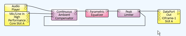
Reference - Connect the program material taken from the output that feeds the amplifier(s) after it has been post-processed by any filters/equalizers and non-linear components such as compressors and/or limiters.
Outputs
Audio signal pins are represented by a () circle, and traditional wiring is represented by a thin black line.
Program - The program material with the Continuous Ambient Compensation gain applied.
Ambient - Monitor output of the actual recovered ambient signal.
- Set the Mic/Spkr Distance control to the distance (in meters) between the sensing microphone and the nearest loudspeaker.
- Play the program material.
- Force the ambient compensator to maximum gain:
- set the Ambient Threshold control at -60 dB
- set the Maximum Gain control to the desired value.
- Adjust the microphone Max RMS Input Level (in the Mic/Line In component) so that the microphone signal level entering the Continuous Ambient Compensator is as high as possible but does not clip. Monitor the clip indicator in the Mic/Line In component.
- The Program Reduction meter shows how much program material is removed from the microphone signal. After at least ten seconds, the reduction should be between -10dB and -20dB. If it isn't, see Notes and Trouble Shooting below.
- Force the Continuous Ambient Compensator to minimum gain:
- set the Ambient Threshold control to 20 dB
- set the Minimum Gain to the desired value.
- With the program material still playing, set the Ambient Threshold control to about 5 dB above the ambient signal level represented by the moving orange dot.
- Now when the ambient signal level rises it will enter the gain region and gain is applied to the program material.
- Adjust the Attack Time control to the desired value. The attack time determines how quickly the gain responds to a rising ambient signal detector level.
- Adjust the Release Time control to the desired value. The release time determines how quickly the gain responds to a falling ambient signal detector level. The Release Time is forced to be greater than or equal to the Attack Time.
- Adjust the gain Ratio control to its desired value. A value of 1 results in a gain change that matches the ambient signal level change. A value of 0.5 results in 0.5 dB of gain change for every 1 dB of ambient signal level change. Likewise, a value of 2 results in 2 dB of gain change for every 1 dB of ambient signal level change.
Continuous Ambient Compensator Properties
Tip: For additional properties that are not listed, refer to the Properties Panel help topic for more information.
Audio Bandwidth
Since lower frequencies are dominant in most ambient signals, the Continuous Ambient Compensator provides the capability of specifying the upper limit of the audio bandwidth used to measure for compensation. Lowering the upper limit of the audio bandwidth causes the compensator to use fewer resources.
This property does not affect the program material audio bandwidth, which is always full bandwidth.
Microphone Filter
Determines if the Mic Filter is active and available in the Control Panel.
Relative Venue Size
This determines the size of the loudspeaker(s)-to-microphone or system response modeler.
The smaller the model, the fewer the processing resources required by the component.
If the Continuous Ambient Compensator does not sufficiently remove the program material from the microphone signal, increase the venue size.
Detector Time Constant
Selects a preset detector time (in seconds), or enables the Detector Time control in the Control Panel.
In Gain (dB)
Adjusts the microphone input level.
Detector (dB)
Displays the ambient level, including any program material present.
Response Panel
Graphically displays the operation of the Continuous Ambient Compensator.
The X axis represents the recovered ambient signal RMS level.
The Y axis represents the dB gain that is applied to the program material.
Bypass
When engaged, the Continuous Ambient Compensator is bypassed.
Gain (dB)
Displays the gain applied to the program material.
Out Gain (dB)
Adjusts the Program output level.
Note: Depending on the Type of filter you select, some of the controls listed below may not be available.
Bypass
When engaged, the Mic Filter is bypassed, the ambient noise is not filtered except by the Audio Bandwidth setting in the Properties.
Type
Selects the type of filter to use. You are able to choose from any of the following:
- Low-Pass
- High-Pass
- Band-Pass
- Band-Stop
- Parametric
- Low-Shelf
- High-Shelf
Bandwidth (Octave)
Sets the width of the frequency band to be filtered. Available only with the Band-Pass, Band-Stop, and Parametric filters.
Frequency (Hz)
Sets the frequency of the filter. For filters that have a bandwidth setting, this is the center frequency of the bandwidth.
The upper limit for this control is either 1.25 kHz, 2.5 kHz, or 5.0 kHz depending on the Audio Bandwidth Property.
Gain (dB)
Sets the gain for the Parametric, High-Shelf, and Low-Shelf filters.
Mic / Spkr Distance (meters)
The distance, in meters, between the microphone and the nearest loudspeaker.
If this control is set to less than the actual distance, the compensator wastes cycles modeling the propagation delay from the loudspeaker to the microphone. If the microphone is not too far from the loudspeaker, the compensator continues to work but with a higher risk of program material leaking into the recovered ambient signal.
If the entered Mic/Spkr distance is greater than the actual distance, the compensator will be unable to model part of the response, and program material will leak into the recovered ambient signal with possible runaway gain as a result.
The Continuous Ambient Compensator works with multiple loudspeakers, provided they are driven with the same program material, and this control is set to the distance to the nearest loudspeaker.
Detector Time (seconds)
The Detector Time control is available when you have selected Use Control for Detector Time Constant in the Properties.
The Detector Time determines the rate of change of the Detector level in response to changes in the ambient input signal.
This adjustment is to prevent changes (spikes, low frequency signals) in the ambient input from causing unwanted, momentary changes in the program output.
Program Cancellation (dB)
This meter shows the amount of program material that the component was able to remove from the sense microphone.
Ambient Threshold (dB)
The recovered ambient signal level at which the compensator starts compensating. (The program material already has been removed.)
Represented in the Response Graph as the lower of the two blue dots. When this control is moved, the blue dot moves horizontally on the X axis.
Ratio
A value of 1 results in a gain change that matches the ambient signal level change.
A value of 0.5 results in 0.5 dB of gain change for every 1 dB of ambient signal level change.
A value of 2 results in 2 dB of gain change for every 1 dB of ambient signal level change.
Minimum Gain (dB)
The minimum amount of gain you want to apply to the Program output when the ambient noise is at it's lowest point. Usually a negative amount, or attenuation - shown in red on the Gain meter. Gain is added to the Program input level up to this setting. If the Minimum Gain is -15 dB, and the Program input level is 5 dB, the Program Output is -10 dB
5 + (-15) = -10
Represented in the Response Graph as the lower of the two blue dots. When this control is moved, the blue dot moves vertically on the Y axis.
Maximum Gain (dB)
The maximum amount of gain you want to apply to the Program output when the ambient noise is at it's highest point. Gain is added to the Program input level up to this setting. If the Maximum Gain is set to 10 dB, and the Program input level is 5 dB, the Program Output is 15 dB.
Represented in the Response Graph as the upper of the two blue dots. When this control is moved, the blue dot moves vertically on the Y axis.
Attack Time (seconds)
Determines the time it takes for the gain to reach 63% of a rising ambient signal detector level.
Release Time (seconds)
Determines the time it takes for the gain to reach 63% of a falling ambient signal detector level.
The available Control Pins depend on settings in Properties.
|
Pin Name |
Value |
String |
Position |
Pins Available |
|---|---|---|---|---|
|
Ambient Detector Level |
-100 to 20 |
-100 dB to 20 dB |
0.000 to 1.00 |
Output |
|
Ambient Microphone to Nearest Speaker Distance |
0 to 10 |
0 mm to 10 m |
0.000 to 1.00 |
Input / Output |
|
Ambient Threshold Level |
-60 to 20 |
-60 dB to 20 dB |
0.000 to 1.00 |
Input / Output |
|
Applied Gain |
0 to 20 |
0 dB to 20 dB |
0.000 to 1.00 |
Output |
|
Attack Time |
1 to 60 |
1 s to 60 s |
0.000 to 1.00 |
Input / Output |
|
Bypass |
0 1 |
active bypass |
0 1 |
Input / Output |
|
Detector Time |
1 to 60 | 1.00s to 60.0s | 0 to 1.00 | |
|
Input Gain |
-20 to 20 |
-20 dB to 20 dB |
0.000 to 1.00 |
Input / Output |
|
Maximum Program Gain |
0 to 20 |
-20 dB to 20 dB |
0.000 to 1.00 |
Input / Output |
|
Microphone Filter Bandwidth |
.010 to 3.00 |
.010 to 3.00 |
0.000 to 1.00 |
Input / Output |
|
Microphone Filter Bypass |
0 1 |
active bypass |
0 1 |
Input / Output |
|
Microphone Filter Frequency |
10 to 5000 |
10 Hz to 5 kHz |
0.000 to 1.00 |
Input / Output |
|
Microphone Filter Gain |
-100 to 20 |
-100 dB to 20 dB |
0.000 to 1.00 |
Input / Output |
|
Microphone Filter Type |
1.00 2.00 3.00 4.00 5.00 6.00 7.00 |
Low-Pass High-Pass Band-Pass Band-stop Parametric Low-Shelf High-Shelf |
0 .167 .333 .500 .667 .833 1.00 |
Input / Output |
|
Minimum Program Gain |
-20 to 0 |
-20 dB to 0 dB |
0.000 to 1.00 |
Input / Output |
|
Output Gain |
-20 to 20 |
-20 dB to 20 dB |
0.000 to 1.00 |
Input / Output |
|
Program Cancellation |
0 to -20 |
0 dB to -20 dB |
0.000 to 1.00 |
Output |
|
Ratio |
0.200 to 2.00 |
.200 to 2.0 |
0.000 to 1.00 |
Input / Output |
|
Release Time |
1 to 60 |
1 s to 60 s |
0.000 to 1.00 |
Input / Output |
- Initially, the compensator needs program material in order for the model to converge to the venue's system response. Depending on the type and frequency content of the program material it may take from a few seconds to over a minute for the compensator to converge to a proper model.
- During this initial calibration, the gain starts at its maximum value and is gradually reduced to its minimum value. Once the model has converged, the compensator will continuously and automatically adjust to any changes in the system response.
- Monitor the recovered ambient signal (Ambient Output). In general, if too much program material is present, increase the value of the Relative Room Size property. If this doesn't improve the ambient signal, make sure the Mic / Spkr Distance control setting is correct and that the distance has been entered in meters.
- If possible, experiment with the distance between the sensing microphone and the nearest loudspeaker. Start with a distance of about 2 meters (6 feet).
- Make sure that the Reference input is connected to the same signal that feeds the final output. (Line Out, DataPort Out, etc.) In particular, there should be no time-varying or non-linear processing such as compressors and / or limiters between the reference signal source and the final loudspeaker signal. Refer to the following example.
- Make sure that none of the signals involved in ambient compensation are clipping. It is highly recommended that the ambient compensator's output signal is post-processed with a peak limiter as shown above.
- If multiple sensing microphones are used, mix them, then feed the mix to the ambient compensator's Microphone input.
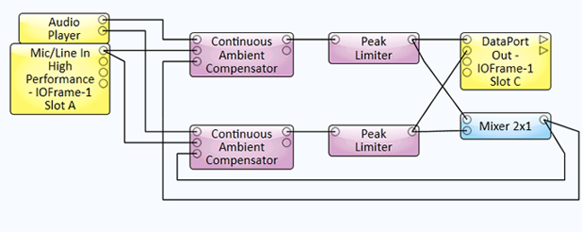
- Do not use multiple independent ambient compensators in the same acoustical zone. They most likely will interact with possible runaway gain as a result. If the program material is multi-channel, mix the reference signal as shown in the (stereo) example shown below. Ensure all control settings on the multiple compensators track.