Signal Wire Tracing
Overview
Signal Wire Tracing (also referred to as Signal Flow Tracing) allows you to visually trace, inspect, and troubleshoot signal paths across a Q-SYS Designer schematic. Simply click any wire or Signal Name tag to view the signal flow highlighted in real time, even across complex, multi-page designs. The tracing engine evaluates the active state of components, including mutes, matrix router crosspoints, gain settings, and logic conditions, to highlight the exact path signals are traveling and where they are stopped.
Note: To use Signal Wire Tracing, the design must be in Run on Core (F5) or Emulation Mode (F6). Signal Wire Tracing is not active in Design Mode (F7).
 Basic Operation
Requirements
To use Signal Wire Tracing, the design must be in either Run (F5) or Emulation (F6) Modes.
Signal Trace Mode must be toggled on in the View Menu of Designer (can be turned off if desired):
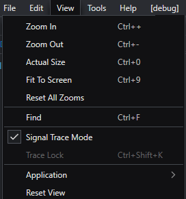
Signal Trace Mode
Default when left-clicking any wire or tag to view signal path/flow immediately.
-
Left-click any wire or Signal Name tag. The complete signal path is immediately highlighted in both directions (upstream to the source and downstream to the destination).
-
To clear, left-click anywhere on the empty schematic canvas to dismiss the active trace.
Note: Tracing works on one selection at a time. Multi-selecting multiple items will not initiate a trace.
Trace From Wire
Use this when you want to explicitly initiate or refresh a trace directly from a component's context menu while accessing other options
-
Right-click any wire or Signal Name tag to select "Trace From Wire". Explicitly starts graph traversal from that exact wire or tag.
Locking a Trace
Locking pins the active trace to the canvas, allowing you to click around, adjust controls, or switch pages without losing your highlighted path:
-
Right-Click: Right-click the traced wire or tag and select Lock Trace.
-
Keyboard Shortcut: Press Ctrl + Shift + K.
-
Menu Bar: Select View > Trace Lock.
Note: While locked, clicking other wires or canvas areas will not clear the trace until you unlock it.
Trace Appearance
Trace Appearance Based on Signal Category
Different signal types display distinct visual styles so you can easily tell them apart:
-
Audio: Continuous Stream - Active audio flowing through connected components.
-
Video: Continuous Stream - Active AV stream routed between video endpoints.
-
Control: "Highway" path pattern - Shows the available route control signals can travel. Because control data is sent in bursts rather than a continuous stream, this highlights the valid communication path.
-
Interrupted / Stopped: Stop indicator / line break - Clearly shows where a signal is blocked by a mute, a bypassed block, or a fader set to ≤ −100 dB.
Customizing Trace Appearance
You can personalize how traces look to match your workspace or accessibility needs under File > Preferences > Signal Tracing with these options:
-
Wire Trace Size: Increase or decrease the line thickness of traced paths for easier viewing on high-resolution displays.
-
Highlight Modules: Turn on bounding-box highlights around components along the active signal path.
-
Category Colors: Change the overall highlight color for each signal category (Audio, Video, Control).
Note: Color settings apply to the entire category (for example, all audio paths share the same audio highlight color).
Additional Features
Additional features to keep in mind when running a large design that splits signal flows across multiple schematic pages using Signal Names:
-
Jump to Destination: Right-click any Signal Name tag and select Jump to [Page Name] to instantly navigate to the connected page. If a single transmitter feeds multiple receivers, a list of available destinations appears for you to choose from.
-
Signal Snakes: Multi-channel Signal Snakes maintain a direct 1-to-1 channel connection. To trace a channel through a snake, click the individual wire entering or exiting the snake block.